CFD meshing terminology can be quite daunting, especially for beginners. This article will give you an overview of the most common CFD meshing terms and expressions we use daily, in alphabetical order. If you are struggling with some of the expressions we are using in our blog posts, you will most likely find your answer below:
Anisotropic mesh generation
Anisotropic mesh generation is a technique used to create computational meshes with different cell sizes in various directions. Unlike isotropic meshing, where the cell size is uniform in all directions, anisotropic meshing allows for a tailored distribution of grid points based on the flow or stress characteristics, depending on the physics of the problem being solved.
In anisotropic mesh generation, the mesh points are concentrated in regions where high gradients or complex flow patterns are expected, while regions with relatively smooth variations may have coarser meshes. This adaptive mesh refinement helps to optimize computational resources by concentrating computational effort where it is most needed while reducing the computational burden in areas of less interest.
Anisotropic meshing can significantly improve the accuracy and efficiency of simulations, especially in problems with highly anisotropic flow or stress fields, such as boundary layer flows, turbulent flows, or free surface flows. By providing better resolution in critical regions, anisotropic meshes enable more accurate capture of flow features or stress concentrations while minimizing computational costs.
Arbitrary polyhedra
The term arbitrary polyhedra refers to geometric shapes composed of flat surfaces, known as faces, that enclose a three-dimensional region. Unlike regular polyhedra, such as cubes, pyramids, or prisms, which have uniform faces and symmetrical properties, arbitrary polyhedra can have irregular faces, varying angles between faces, and non-uniform edge lengths. The term “arbitrary” indicates that these polyhedra can have diverse shapes and configurations, limited only by the constraints imposed by their defining vertices, edges, and faces. This flexibility makes arbitrary polyhedra highly versatile and applicable in a wide range of engineering, scientific, and computational contexts.
Furthermore, arbitrary polyhedra facilitate adaptive meshing strategies, where the mesh resolution can be refined or coarsened locally based on the desired level of accuracy or computational efficiency. This adaptability is particularly valuable in simulations involving fluid flows over complex surfaces, where capturing boundary layers and flow features accurately is essential.
Boundary layer
A boundary layer is a thin region adjacent to a solid surface, within which the flow of a fluid (gas or liquid) experiences significant changes in velocity and other flow properties compared to the bulk flow away from the surface. This phenomenon occurs due to the effects of viscosity, which causes fluid molecules to adhere to the solid surface and create a shear stress at the interface between the solid and fluid.
In the boundary layer, the velocity of the fluid varies gradually from zero at the solid surface to the velocity of the free stream away from the surface. This velocity gradient results in layers of fluid moving at different speeds, with the layer closest to the surface moving slowest and the outer layer experiencing the freestream velocity.
Boundary layers are classified into two main types:
- Laminar Boundary Layer: In a laminar boundary layer, fluid particles move in smooth, parallel layers along the surface, with minimal mixing between adjacent layers. The flow remains orderly and predictable until a critical point where it transitions to turbulent flow due to disturbances or increasing flow velocity.
- Turbulent Boundary Layer: In a turbulent boundary layer, the flow becomes chaotic and characterized by fluctuations in velocity and pressure. Turbulent eddies and vortices dominate the flow, leading to increased mixing of fluid particles and higher rates of momentum and energy transfer. Turbulent boundary layers are more common in practical applications and are associated with higher drag and heat transfer rates compared to laminar boundary layers.
The outer boundary layer is a very useful option in our boundary layer library. Mostly it is used in aerodynamic and heat transfer applications, where a fine boundary layer near the wall is desired. Its role is to provide a smooth transition between the finer inner part of the layer and the internal mesh.
Case Preparation
Part of a pre-processing phase. It takes a lot of time, but the effort is worth it and can be seen in the result.
cfMesh
A library for mesh generation implemented within the OpenFOAM framework, freely available for download. Developed by Creative Fields Holding, Ltd.
CF-MESH+
Automatic meshing workflow software with an intuitive user interface. 14-day free trial available.
Designed for engineers and other experts using CFD in their product development and research. It is a perfect companion for those who require an efficient, easy-to-use, yet fully automated meshing process able to resolve complex domains faced in industrial settings.
The volume meshes generated by CF-MESH+ are delivered in OpenFOAM, ANSYS Fluent, or neutral (CGNS) formats, and are highly suitable for use by a multitude of popular CFD software. The meshes have been successfully used in various types of CFD simulations, from automotive aerodynamics (see e.g. our F1 car case study or Ahmed body meshing example video), hydrodynamics, human hemodynamics (blood vessels), HVAC, to chemical processing, or civil engineering. Due to its ability to generate volume meshes composed of tetrahedral elements only, the software has also found successful usage within the finite element analysis (FEA) realm.
Developed by Creative Fields Holding, Ltd.
Convection term
The convection term is often the largest source of discretisation errors in the solution of fluid flows, especially in the momentum equation because of its non-linear nature (the velocity is transported by itself). The accuracy is dependent on two important aspects:
- Mesh quality and resolution – for more information, read our previous posts on mesh quality and skewness
- Interpolation scheme – numerous schemes have been developed to achieve an accurate solution and avoid unphysical solutions.
Discretisation
In computational fluid dynamics (CFD), the governing equations describing fluid flow, such as the Navier-Stokes equations, are continuous partial differential equations (PDEs). To solve these equations numerically, the spatial domain is discretized into a mesh of discrete cells or elements, and the equations are evaluated at discrete points within each cell. This allows engineers to analyze the behaviour of complex flows under various boundary conditions.
DrivAer
The generic DrivAer model for external flow was introduced in 2011 at TU München, to narrow the gap between the overly-simplified models commonly used in automotive aerodynamics investigations (e.g. Ahmed body) and the highly complex production cars.
Face uniformity
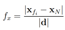
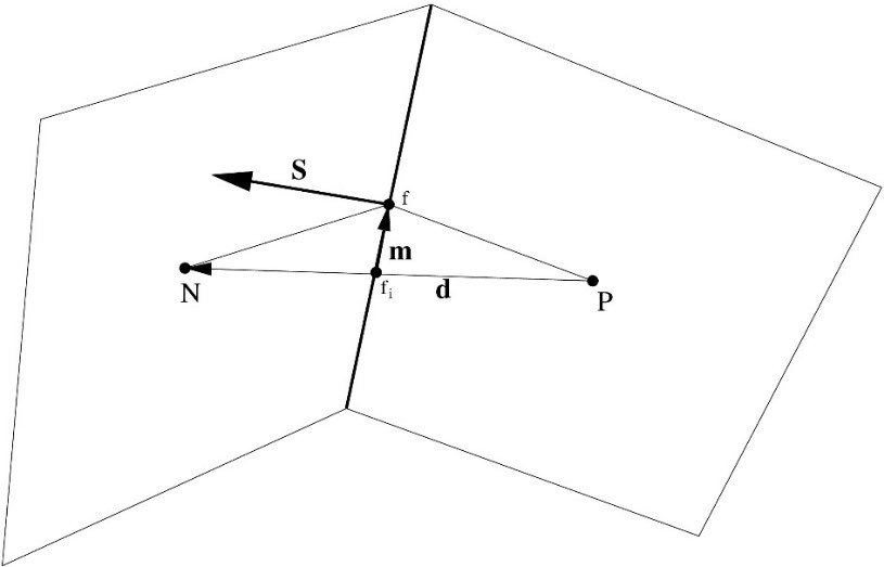
Face-uniformity is measured as a ratio of the distance from the face centre to the neighbour cell centre over the distance between the cell centres.

Where xfi and xN are the face centre and the neighbour cell centre, respectively, as shown in the figure above. The ideal value is 0.5. It is beneficial to keep the uniformity as close to 0.5 as possible! Lower values do not make the mesh invalid. However, it harms accuracy!
Feature edges
The feature edges are surface mesh sub-elements whose existence is often very important in the meshing process – where they are treated as constraints. These are the sharp corners/edges in the domain which, when specified as feature edges, cause the software to capture them closely during the meshing process. We recommend creating the feature edges, where they are essential, even though they do not exist in the real world.
FVM – Finite Volume Method
The Finite Volume Method (FVM) became popular in CFD due to its conservative properties.
Gap handling
In computational simulations, small gaps require fine mesh resolution. Mesh adaptation or refinement techniques can be employed to locally refine the mesh in areas with gaps or discontinuities, ensuring that the simulation captures the relevant features accurately. The usage of automatic mesh refinement reduces the burden of the user required to set up the mesh.
Hex-dominant meshers
Hex-dominant meshers employ specialized algorithms used in computational mesh generation, particularly in computational fluid dynamics (CFD), to generate predominantly hexahedral (hex) elements in the mesh. Hexahedral elements are three-dimensional elements with six quadrilateral faces, and they offer several advantages over other types of elements, such as tetrahedral or polyhedral elements, including better numerical stability, accuracy, and efficiency in many types of simulations.
The term “dominant” in hex-dominant meshers refers to the fact that these algorithms prioritize the generation of hexahedral elements whenever possible while still allowing the inclusion of other element types to handle complex geometries or regions where hexahedral meshing is not feasible or efficient. This approach aims to harness the benefits of hexahedral elements while maintaining flexibility and adaptability to accommodate geometric complexities.
Input geometry
In computational fluid dynamics (CFD) meshing, the input geometry refers to the three-dimensional representation of the physical object or domain for which the fluid flow is to be simulated. It is most often a surface triangulation or a CAD format.
Laplacian terms
The Laplacian of a function represents the divergence of its gradient. It measures the local rate of change of the function and is often used to describe phenomena related to diffusion, dispersion, or the equilibrium of physical quantities in space.
Laplacian terms are discretized in numerical simulations using finite difference, finite volume, or finite element methods, depending on the specific numerical scheme employed. Accurate representation of Laplacian terms is crucial for capturing diffusion phenomena accurately and obtaining reliable results in CFD simulations or numerical analyses involving diffusion processes.
Linear interpolation
Linear interpolation (also called Central Differencing – CD) is a natural second-order interpolation practice:

Mesh modifiers
cfMesh is implemented by using a concept of mesh modifiers, which is extensible and allows for efficient parallelization using both shared memory parallelization (SMP) and distributed memory parallelization using MPI.
Mesh modifiers provide users with capabilities to improve mesh quality, adapt mesh resolution, and tailor the mesh to specific simulation requirements.
Mesh quality metrics
Mesh quality metrics are used for checking the quality of the mesh for numerical simulations.
Mesh Refinement
Mesh refinement is a process in computational mesh generation where the resolution of the mesh is increased in specific regions of interest to capture local flow features or geometric details better. It involves subdividing existing mesh elements or adding new elements to enhance the spatial resolution and accuracy of a numerical simulation,
The goal of mesh refinement is to ensure that the computational mesh adequately represents the underlying physics or geometry of the problem being simulated. By increasing the mesh resolution in critical areas, mesh refinement helps improve the fidelity of the numerical solution and enables more accurate predictions of flow behaviour, stresses, or other physical quantities.
Mesh refinement can be performed using various techniques, including:
- Local Refinement: Local refinement involves increasing the mesh density in specific regions of interest where high solution gradients, complex flow behaviour, or geometric details are present. This can be achieved by subdividing existing elements or adding new elements to refine the mesh locally.
- Adaptive Refinement: Adaptive refinement dynamically adjusts the mesh resolution during the simulation based on solution variables, error indicators, or predefined criteria. It refines the mesh in regions where the solution requires higher resolution and coarsens the mesh in areas where the solution is smooth or where computational resources need to be conserved.
- Feature-based Refinement: Feature-based refinement targets geometric features, such as sharp corners, edges, or regions of high curvature, and increases the mesh density around these features to capture them accurately. This ensures that the mesh conforms closely to the geometry and maintains high fidelity in regions with complex shapes.
- Error-driven Refinement: focuses on regions where rapid changes in flow variables or physical quantities occur. Increasing mesh resolution in these regions improves the accuracy of the numerical solution and helps capture important flow features, such as shocks, boundary layers, or vortices.
Mesh templates
Cartesian (2D and 3D), tetrahedral, and polyhedral.
Multi-domain meshing
This feature enables you to create meshes with conformal interfaces between the multiple domains present in the geometry. You can easily create both patches or face zones at a multi-material interface. This is crucial for complex simulations of real-life examples like calculating the hydrodynamic performance of boats, turbine performance, or examples of heat exchange in multi-material simulations e.g. cooling of electric vehicle batteries with air/fluids.
Non-orthogonality

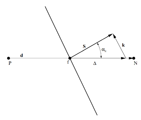
Non-orthogonality is measured as the angle between the vector connecting neighbouring cell centres at the face and the face-area vector, see the figure below. Low non-orthogonality angles are desired. However, if the non-orthogonality increases about 90 degrees, the mesh becomes invalid and the discretisation is no longer conservative because the vector connecting cell centres and the face start pointing in opposite directions!
Refinement settings
Refinement settings in CFD meshing refer to the parameters and criteria used to control the process of mesh refinement. These settings dictate how and where the mesh should be refined to achieve desired levels of resolution and accuracy in the computational domain. Refinement settings are crucial for obtaining reliable and accurate results in CFD simulations, as they determine the quality and fidelity of the mesh.
Here are some common refinement settings used in CFD meshing:
- Global Refinement Level: This setting controls the overall mesh resolution by specifying the global level of refinement applied to the entire computational domain. A higher refinement level results in a denser mesh with smaller elements, while a lower refinement level produces a coarser mesh with larger elements. Global refinement level settings provide a coarse control over mesh resolution.
- Local Refinement Criteria: Local refinement criteria define conditions or parameters that trigger mesh refinement in specific regions of interest within the domain. These criteria may include gradients of flow variables (e.g., velocity, pressure, temperature), proximity to solid boundaries, regions of high vorticity or turbulence, or other flow features deemed important for accurate simulation results.
- Adaptive Refinement: Adaptive refinement settings enable the mesh to dynamically adjust its resolution during the simulation based on solution variables or error indicators. Adaptive refinement techniques refine the mesh in regions where solution gradients are high or where errors exceed predefined thresholds while coarsening the mesh in regions with low solution variation. This allows for efficient allocation of computational resources and ensures optimal mesh resolution where it is most needed.
- Boundary Layer Refinement: Boundary layer refinement settings focus on refining the mesh near solid boundaries to capture boundary layer phenomena accurately. These settings specify the thickness and resolution of boundary layer meshes and control the transition from the boundary layer to the outer flow domain. Boundary layer refinement is essential for capturing viscous effects and resolving velocity gradients near walls.
- Feature-Based Refinement: Feature-based refinement settings target specific geometric features or structures within the domain, such as sharp edges, corners, or geometric discontinuities. These settings ensure that the mesh accurately captures the geometry’s details and maintains geometric fidelity in the simulation.
- Quality-Based Refinement: Quality-based refinement settings control mesh refinement based on mesh quality metrics, such as element aspect ratio, skewness, or orthogonality. These settings aim to improve mesh quality and stability by refining elements that deviate from desired quality criteria.
By configuring refinement settings appropriately, users can tailor the mesh to specific simulation requirements, optimize solution accuracy and efficiency, and obtain reliable and robust results in CFD simulations.
Skewness

Skewness is measured as the relative distance between the face centre and the point where the line connecting the neighbouring centres of a face intersects the face and the distance between the neighbouring cell centres. It does not affect the validity of a mesh. However, lower values are desired!
SMP – shared memory parallelization
Often used as a term for a code using multiple threads.
Surface-normal gradient schemes
The scheme for evaluation of surface-normal gradients affects the accuracy of Laplacian terms, and it depends on the non-orthogonality.
Most often, the evaluation of the surface-normal gradient is performed as follows:

where the first term on the right-hand side is treated implicitly and the second term, representing the non-orthogonality contribution, is treated explicitly as a source term within the solver. This means that it is beneficial to keep non-orthogonality as low as possible to reduce the need to solve equations multiple times until they converge.
Upwind differencing
Upwind differencing (UD) is a first-order interpolation practice introduced to ensure boundedness.
UD is a numerical discretization technique commonly used in computational fluid dynamics (CFD) to approximate the convective transport terms in the governing equations of fluid flow. It is particularly effective for solving hyperbolic partial differential equations (PDEs) that describe the advection of fluid properties, such as the convection-diffusion equation or the Euler equations of inviscid flow.
The key idea behind upwind differencing is to approximate the advection term by considering the direction of flow and using information from the upwind side of the flow to update the solution. This approach helps to maintain numerical stability and accuracy, especially in regions where the flow is predominantly in one direction.


