In order for CF-MESH+ to do its work the best it can and generate high-quality meshes, there are certain requirements that need to be done, when preparing a geometry for meshing. It is possible to do so with some tips and tricks for a high-quality meshing process.
Here are our five tips to make your meshing as smooth as possible:
- Apply cell size smaller than half of the gap dimension
- Modify the geometry where the feature size tends to zero
- Delete duplicate faces in the geometry
- Remove the unnecessary feature edges
- Add feature edges on locations where they are needed
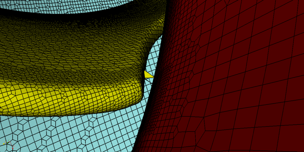
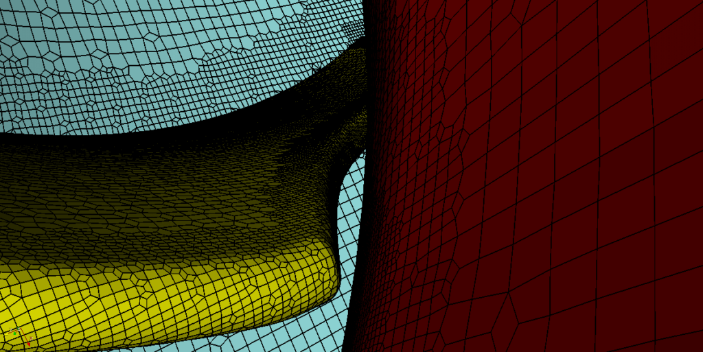
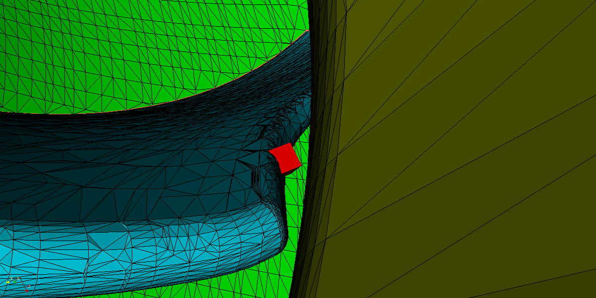
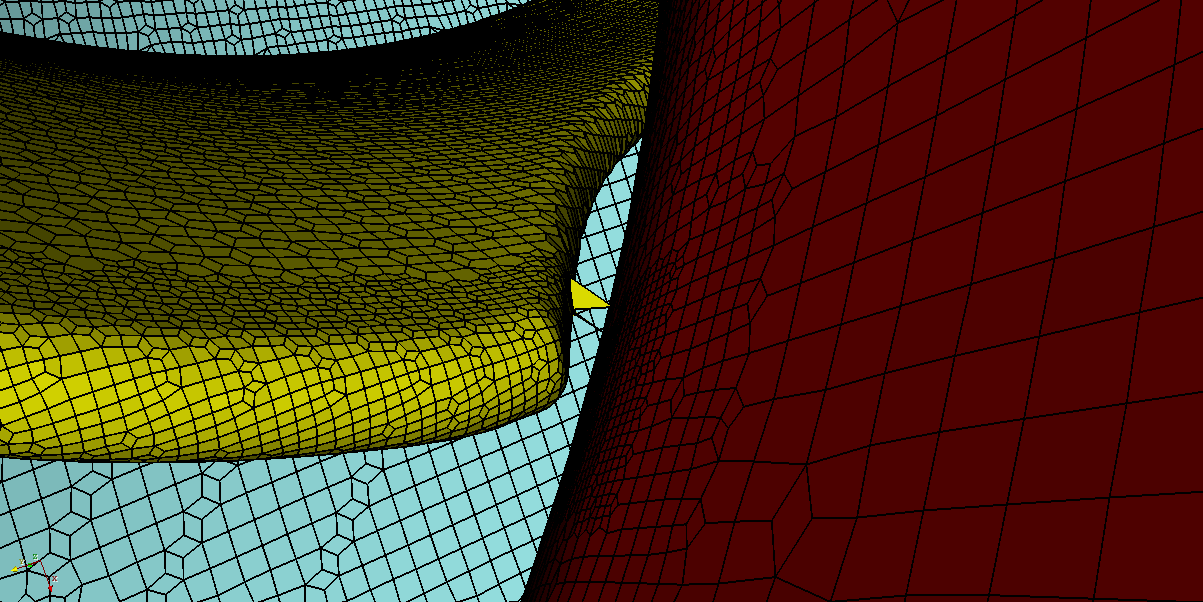
1. Apply cell size smaller than half of the gap dimension
Adjusting a cell size to the geometry is essential to preserve the surface mesh features in the volume mesh. For example, let us take a look at a small gap between the shroud and the blades of a centrifugal compressor. If inappropriate (too big) cell size is applied in this region, the mesher might connect the boundaries together at some places, and the accuracy of the simulation would be affected. To avoid this scenario, at least two rows of cells should be present, i.e. cell size should be less than half the distance between the two boundaries.


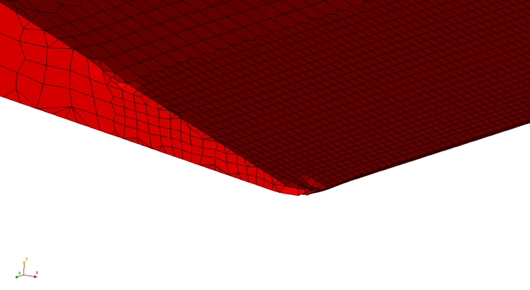
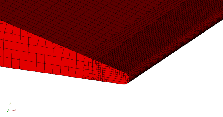
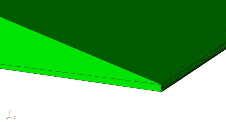
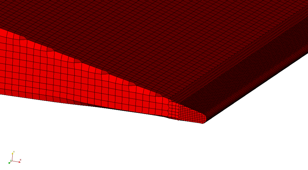
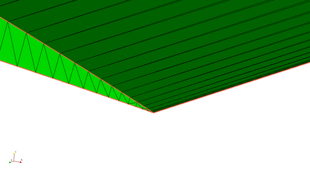
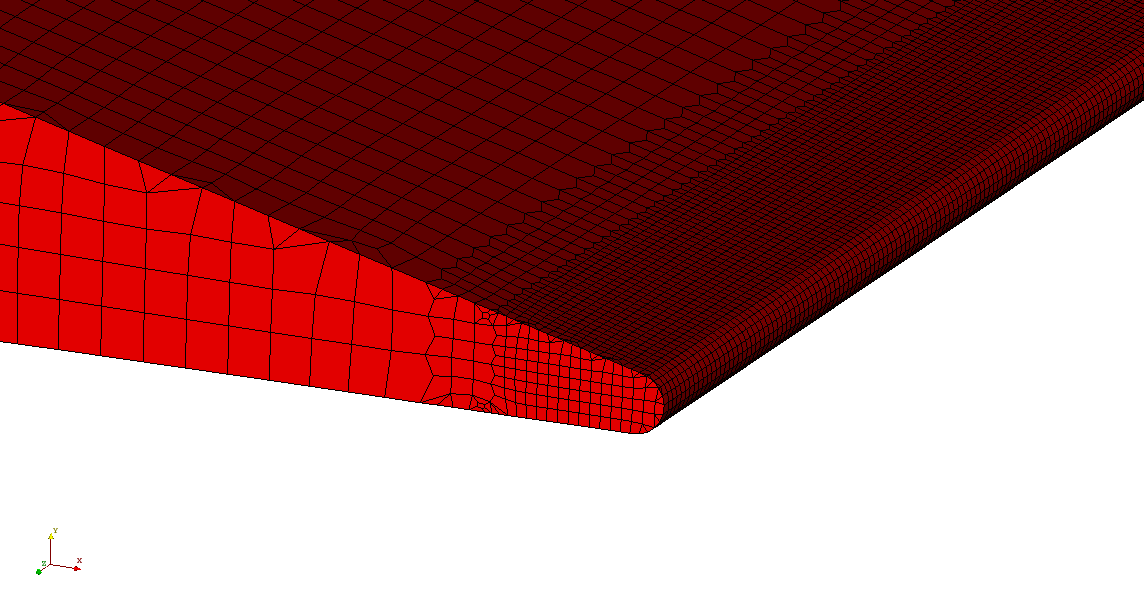
2. Modify the geometry where the feature size tends to zero
This situation is often encountered on trailing edges of airfoils and wings. When a trailing edge is sharp, with an acute angle between the upper and lower surface, no matter how small the cell size is applied, there will be a certain distortion of the geometry. No matter how fine the cells are refined there, they will always be larger than the feature size when approaching the feature edge. This can be solved by modifying the geometry by creating a rounded or blunt trailing edge. This way, the feature size at the trailing edge will be finite, and appropriate cell size can be applied to preserve the geometry. The cell size at the edge should be smaller than half the distance of the lower side and the upper side, at the location where the modification is performed.

The second example is similar and related to the tendency of the feature size to zero but on the other side of the geometry. The problem arises, for example, when mesh is to be generated between two boundaries, connected over the edge with a small angle. Again, the local refinement of the mesh will not solve the problem. Modifying the common edge between the faces, by filleting or chamfering with an application of appropriate cell size, will make it easier for the mesher to handle it.
3. Delete duplicate faces in the geometry
Cleaning a surface mesh from duplicate faces is very important for the mesher to smoothly recognize defined patches. Duplicate faces can cause severe problems in multi-domain meshing. In addition, unwanted feature edges on duplicate faces can put unnecessary constraints on the meshing process. Finally, overall mesh preparation procedures in CF-MESH+ GUI will be simplified (especially the definition of subsets that will be used for local refinement) if the surface mesh is cleaned from duplicate faces. Nevertheless, while deleting redundant faces, it is important to check if this operation will cause unwanted gaps in the geometry.
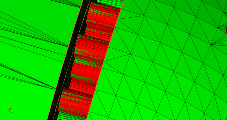
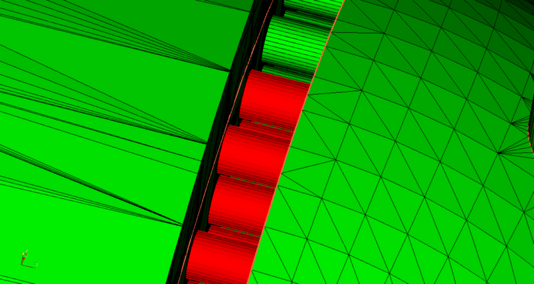
4. Remove the unnecessary feature edges
When a new geometry with complex triangulation is imported, the feature edge detection algorithm may tag some edges as feature edges, even though there is no need for that. If such edges exist, we recommend deleting them from feature edges. In most cases, redundant feature edges will not jeopardize the meshing process, but they can put unnecessary constraints on the process, and in more complex cases, when these edges are close to patch boundaries, it can cause wrong patch detection. In Figure 11. below, unnecessary feature edges that should be deleted are shown on the blades of the compressor.
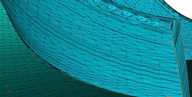
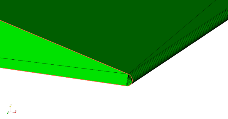
5. Select feature edges where they are needed
The feature edge detection algorithm will detect most of the edges that should be feature edges when the geometry is imported, but it is wise to take a quick look at the surface mesh if there are still edges that should be included in feature edges. Lack of feature edges will cause the loss of geometry features preservation to some extent at these locations, but the mesher will nevertheless work without problems. In the following figures, the wing geometry is used again where feature edges are removed on the side of the wing.
I hope that you have found this post useful and that it has made you curious to try out our latest CF-MESH+, designed to alleviate the pain of meshing. You can also subscribe to our newsletter to stay informed on our newest developments.
- cfMesh 1.2 Released — Introducing a Full GUI for Streamlined Meshing Workflows
- How to install a trial version of CF-MESH+
- Our best meshing practices for high-quality CFD simulations
- Is it always the mesh? Part 7: Volume Ratio – the Secret Killer Nobody Talks About
- Automatic Acute Edge Detection and Fillet Creation Algorithm
")
