1. Introduction
Computational Fluid Dynamics has undergone rapid development in the last two decades. The problems that can be solved with it range from simple laminar flows to very complicated multi-phase flows including heat exchange.
CF-MESH+ multi-domain feature enables you to create meshes with conformal interfaces between the multiple domains present in the geometry. You can easily create both patches or face zones at a multi-material interface. This is crucial for complex simulations of real-life examples like calculating the hydrodynamic performance of boats, turbine performance, or examples of heat exchange in multi-material simulations e.g. cooling of electric vehicle batteries with air/fluids. We will explain more in the following tutorial:
2. Mesh creation using patches
2.1 Creating patches
After you start CF-MESH+ and import the geometry, you can create the patches that define the domains. Geometry in this case represents one surface cube inside the other.
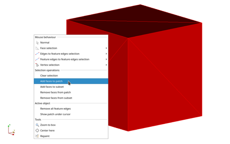
To define the patches you can right-click inside the viewer window and choose the wanted face selection method and behavior.
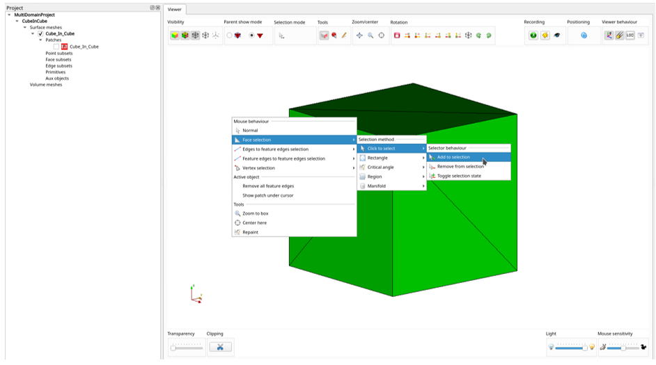
Then select all the faces on the outer geometry by clicking on each triangle on the surface. Now when you right-click on the viewer window again, “Selection operation” features appear and since we are creating patches, choose to add the faces to the patch.
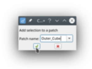
Now we have created a new patch called “Outer_Cube”, and if we enable only “Cube_In_Cube” in the project tree, you can see that it now represents the inner cube (because by creating the “Outer_Cube” patch we removed it from the “Cube_In_Cube” patch).
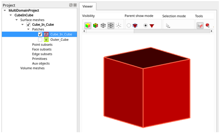
So just rename the patch by double-clicking on its name and changing it to “Inner_Cube”.
2.2 Domain settings
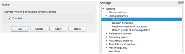
To create domain settings, go to Domains/baffles → Global in the Settings tree. First, you can check the “Enabled” box to “Activate meshing of multiple domains/baffles”.
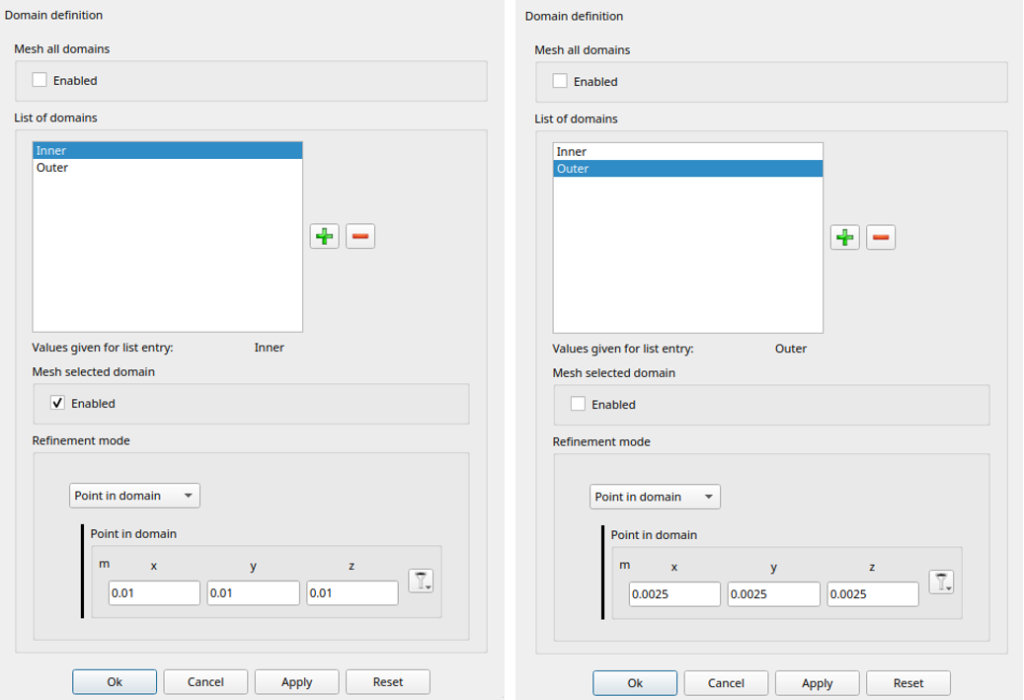
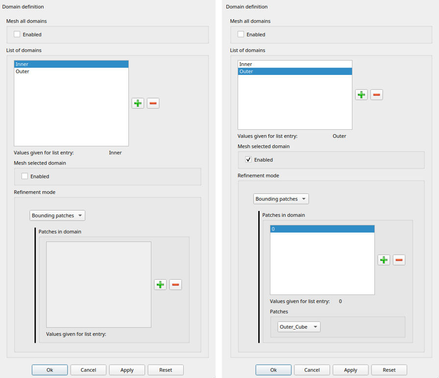
Then go to Domains/baffles → Domain Definition and add two “Domain names” (“Inner and “Outer”). Check “Enabled” in “Mesh all domains” since we are meshing all volume regions. The “Domain definition” window expands after the last step with given values for each domain as shown in the picture below. In “Domain definition mode” you can choose between the “Bounding patches” or “Point in domain”. In this case, we can define the domain using the “Bounding patches” we created earlier. To define the “Inner” domain click on “Inner” in “List of domains”. Then add one patch (0) to “Patches in domain” and choose the wanted patch from the “Patches” drop-down menu (“Inner_Cube”) and click “Apply”. After that, we repeat the same process for the Outer domain and click “Ok” when finished.
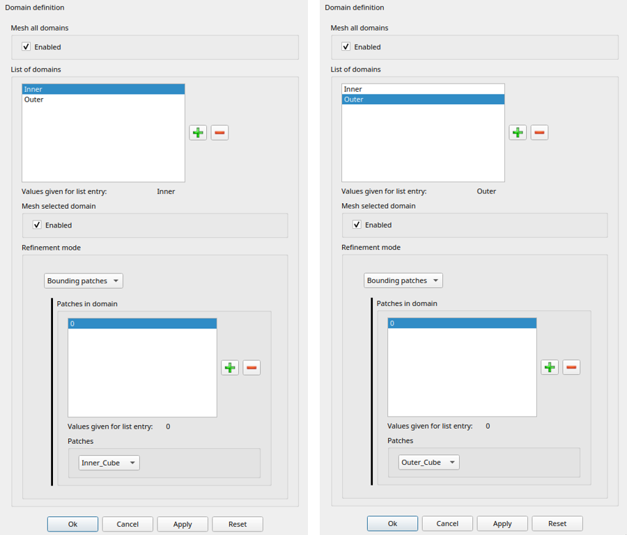
As you saw in the “Creating patches” chapter, the “Inner_cube” patch touches both domains, so the algorithm that selects which domain to use in a specific example of a given patch first tries to find a unique patch to the given domains (a patch that is connected only to one domain), that domain (in this case “Outer”) is later eliminated when the algorithm is choosing whether to mesh “Outer” or “Inner” domain for a given patch.
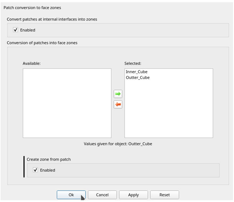
The next step is to define whether you want to convert patches to cell zones or not. Here we selected both available patches but, as we will show later, only the patches of type “Patch” will be converted into face zone (in this case it is Inner_Cube).
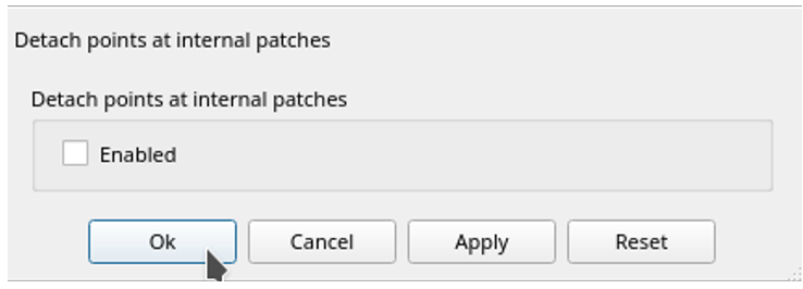
The last setting in the “Domains/baffles” settings tree is “Detach points at internal patches” which allows the user to detach vertices at internal patches. This is necessary for sliding interfaces when meshes are moving relative to each other. This is something we won’t need for the given geometry so just click “Ok”.
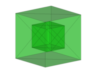
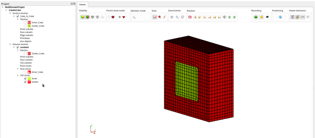
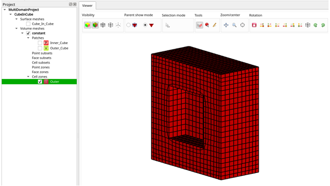
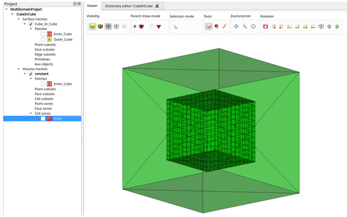
Finally, we can start the meshing process by running Cartesian 3D. As you can see in the picture below, there is one “Face zone” and two “Cell zones” created. Although we chose both patches to create “Face zones”, only the patch that was of type “Patch” is converted as mentioned earlier. Cell zones represent the defined domains and a cut-through view is shown in the picture below.
3. Mesh creation using point in the domain
For simplicity, we are going to use the geometry shown in the previous example. Sometimes it can be hard to find the right points in a domain, especially if you are working with really complex geometry with multiple domains needed. But for simple geometries like this one, it is easier to define the domains using a point in a domain because we don’t need to create patches. We can repeat the first step of “Domains/baffles” → “Global settings” as shown in the previous example where we enable the meshing of multiple domains. The dimensions of the outer cube are 0.02×0,02×0.02 m and the inner cube is two times smaller and positioned in its center. You could help yourself find the right points with “Tools” in the Viewer ribbon (“Point under the cursor” or “distance measure tool”).
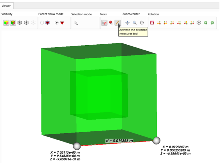
These tools snap to an active surface if you click on it and since we look for a point inside the domains we can not precisely find the points we need using the “point in domain”/”measurement tool”. After we choose the points on the inside of the domains, we can define them. In “Domain/baffles” → “Domain definition”, choose “Point in domain” in the “Domain definition mode” drop-down menu which leads us to the “Point in domain” entry window. Same as in the previous example, first click on the domain we are defining, e.g. “Inner” and then define the point, click “Apply” and switch to “Outer” in “List of domains” to define its point values.
There is another useful tool to find the right points inside a “Domain definition”→ “Point in domain” setting. Next to the point entry window, there is a button for enabling “Show/hide point location”.
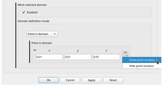
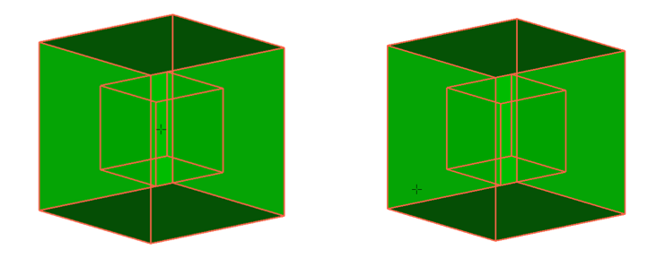
“Show point location” shows you the exact location of a point you defined in the viewer window. You can rotate the body and make sure you define it correctly. In this example, meshing results are the same as in the previous case.
4. Mesh selected domain
Again we are using the same geometry as in the previous two cases. But now we are going to show how to mesh only selected domains. First, we are going to mesh only the “Outer” cube. Go to “Domain/baffles” → “Domain definition”, make sure that the “Mesh all domains” feature is disabled, then select “Inner” in “List of domains” and make sure that “Mesh selected domain” is unchecked as well. After that click “Apply”, choose “Outer” in “List of domains” and define it using “Bounding patches” or “Point in the domain” as shown in the previous two examples.
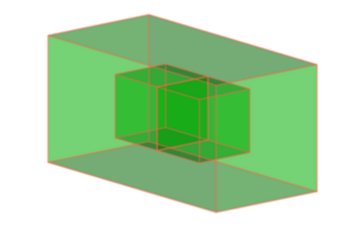
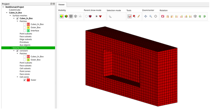
Now we only have one “Cell zone” in the results which is called “Outer” as you can see in the picture below. The previously meshed inner cube is now empty and has no cells.
If you select the “Inner_Cube” patch as a “Bounding patch” in the domain definition, you would end up with only the inner cube meshed, but there would also be a surface of the “Outer_Cube” patch on the outside. You can notice that the algorithm that selects which domain to mesh when there are two or more domains that touch the selected patch, gives an advantage to the domain that represents an enclosed volume surrounded by that patch (in this case both domains touch the selected patch, but the inner cube has meshed).
5. Importance of unique patches
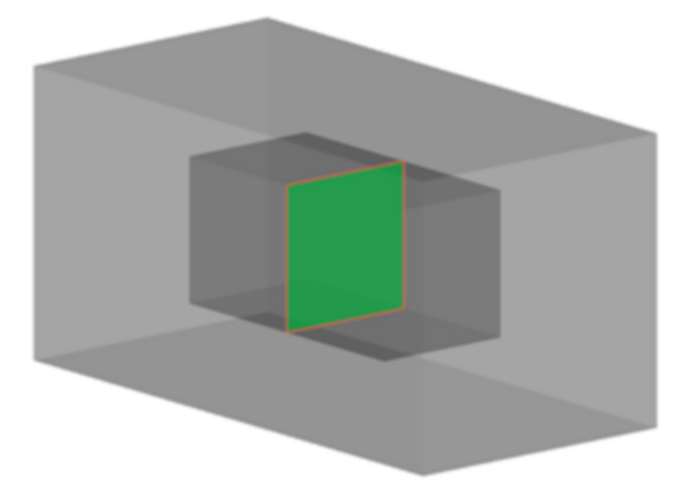
For this example, the geometry represents two cubes, one next to another surrounded by a box. We are using this example to emphasize the importance of having unique patches for defining specific domains.
First, we will show you what happens when you don’t use unique patches to define the domains. In this example, we will try and define the domains of the inner cubes using a face between them.
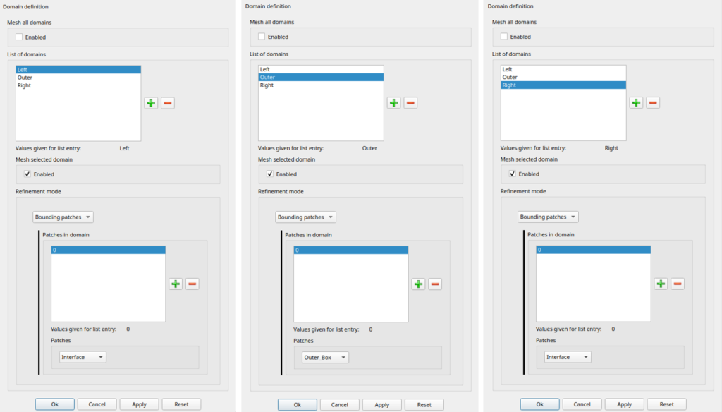
For this example we are using two patches in “Domains/baffles” settings, the first one is “Interface” as seen in the picture above and the second one is the “Outer_Box”. In the “Domain definition” settings window we are going to disable the “Mesh all domains” feature and use only “Mesh selected domains” as seen in the pictures below.
After we complete the meshing process with these settings, only the “Outer” domain has meshed, because the “Left” and “Right” domains don’t have any unique patches defining them.
If we enable “Mesh all domains” in this example we end up with all three domains being meshed, but only the outer domain would be named “Outer” in “Cell zones”. The two cubes on the inside would get generic names (“__unnamed_domain_0”, “__unnamed_domain_1”, …).
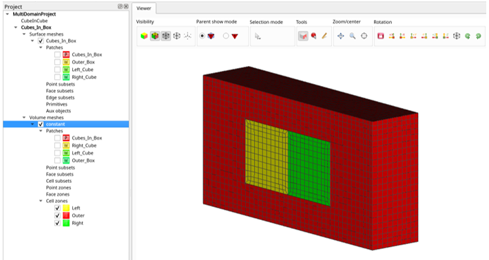
To mesh the domains as defined we have to create the patches so that they have at least one face in a patch that is unique to the given inner domain. As we said earlier, the algorithm can eliminate the “Outer” domain because it is created using a unique patch that represents the outer surface and does not represent a boundary to any other domain. So to define inner patches (“Left” and “Right”) we just have to make sure that they have at least one unique face defined in a patch, in relation to each other. For example, we can do it by defining “Left” and “Right” with patches shown in the picture below (“Left_Cube” and “Right_Cube”).
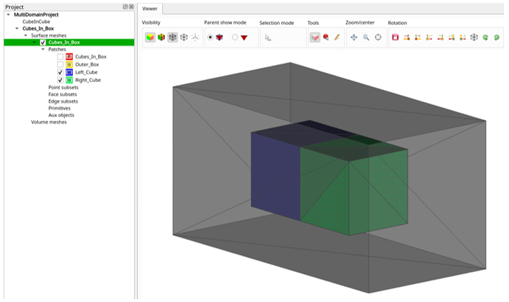
Now we can assign “Left_Cube” and “Right_Cube” patches to “Left” and “Right” domains in “Domain definition”, and “Outer_Box” to “Outer” domains as it is in the previous example also. After completing the meshing process with these settings we get three domains that are defined correctly.
6. Conclusion
This report explained how to define and create multi-domain meshes using CF-MESH+. You only need a geometry with more than one enclosed volume to create multi-domain meshes. To define mesh domains you can use patches or points in the domain. While defining domains using patches, make sure that the given patch has at least one face that is unique to the given domain. You can also let CF-Mesh+ do it automatically using just the “Mesh all domains” feature in “Domain Definition”.
I hope that you have found this post useful and that it has made you curious to try out CF-MESH+ and its multi-domain meshing feature. You can also subscribe to our newsletter to stay informed on our newest developments.
- cfMesh 1.2 Released — Introducing a Full GUI for Streamlined Meshing Workflows
- How to install a trial version of CF-MESH+
- Our best meshing practices for high-quality CFD simulations
- Is it always the mesh? Part 7: Volume Ratio – the Secret Killer Nobody Talks About
- Automatic Acute Edge Detection and Fillet Creation Algorithm
")
