Introduction
Anisotropic meshing enables engineers to craft meshes that adapt to flow characteristics. By finely adjusting mesh resolution along specific directions, aligned with flow patterns and gradients, engineers can significantly enhance both efficiency and accuracy simultaneously. That is why, in CF-MESH+ 5.1.0, we have introduced a completely new methodology for anisotropic meshing refinements. Now you can set general additional refinement levels but also the additional refinement levels in X, Y, and Z directions for a given primitive object.
Marine hydrodynamics simulation exemplifies a problem that can experience substantial enhancements in both efficiency and accuracy through the utilization of anisotropic meshing. That is why we will demonstrate the new feature using an example of a KCS hull case setup.
Geometry
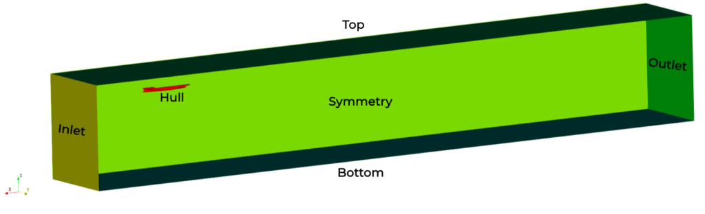
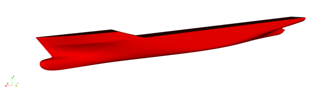
As previously mentioned, we are utilizing the KCS hull geometry. Consequently, there is no requirement for alterations to the geometry itself, we only need to incorporate a necessary bounding box and generate patches using one of the “Selection modes” provided within the CF-MESH+ GUI.
KCS hull dimensions: 116x16x12 m
Anisotropic meshing process
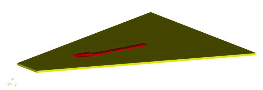
Rather than delving into every setting of a provided case, I will focus solely on the new features and a couple of settings relevant to marine hydrodynamics. In this case, we’ve incorporated several primitive objects for refinement. Initially, we’ve established three distinct tapered boxes dedicated to refining the free surface in areas where waves are anticipated to develop. Considering the estimated angle of wave propagation at 19.5 degrees, we’ve utilized tapered boxes configured as outlined in the following pictures:
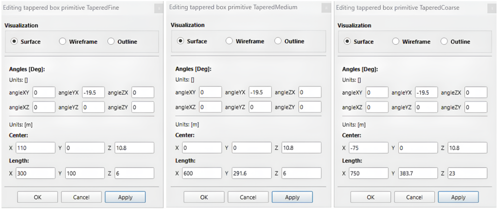
| Tapered box names | “TaperedFine” | “TaperedMedium” | “TaperedCoarse” |
| Additional refinement levels | 7 | 4 | 3 |
For tapered boxes, we have opted to utilize only general additional refinement levels. This decision is due to the unpredictable nature of flow patterns and gradients in regions proximate to the ship hull.
Next, we’ve introduced two box primitives intended for anisotropic refinement of the free surface, with configurations specified in the following pictures:
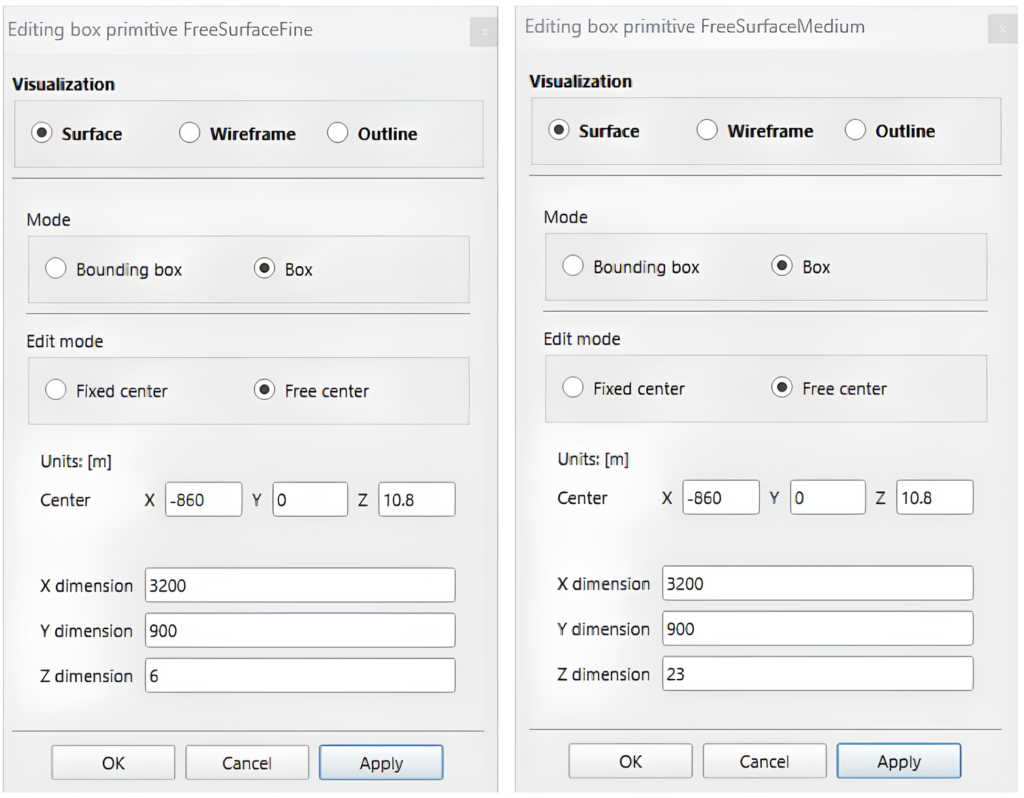
| Free surface box names | “FreeSurfaceFine” | “FreeSurfaceMedium” |
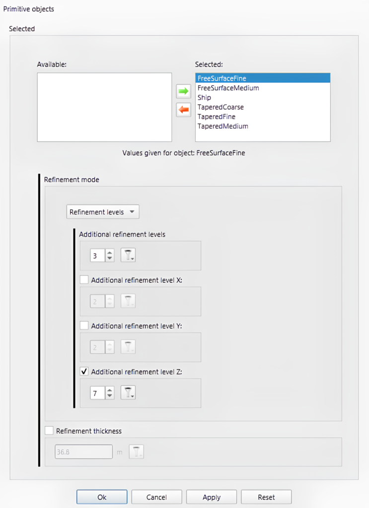
| Additional refinement levels | 3 | 2 |
| Additional refinement level Z | 7 | 5 |
To access the new methodology for anisotropic refinement, navigate to Settings -> Refinement sources -> Primitive objects. Here, you can configure additional refinement levels in the X, Y, and Z directions, as well as the previously available general additional refinement level.
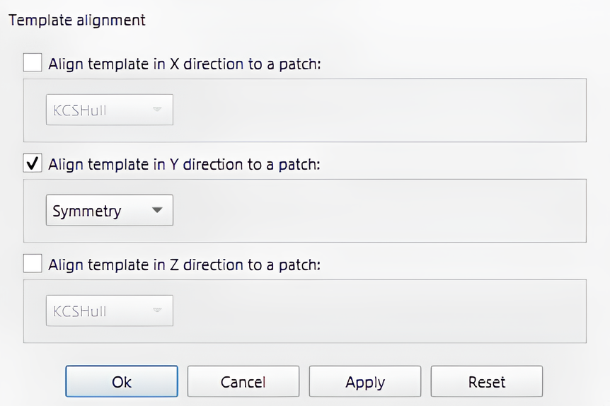
In addition to the new anisotropic methodology, CF-MESH+ 5.1.0. introduces another new feature: “Template alignment” (Settings->Template mesh controls->Template alignment). This functionality enables you to align the initial mesh template with a specified flat patch in a particular direction (X, Y, or Z). This feature can be particularly beneficial, especially for symmetry planes where obtaining high-quality anisotropic cells is important, as illustrated in this example. However, users have the flexibility to set template alignment in all three directions if they deem it necessary to enhance mesh quality at desired boundary patches.
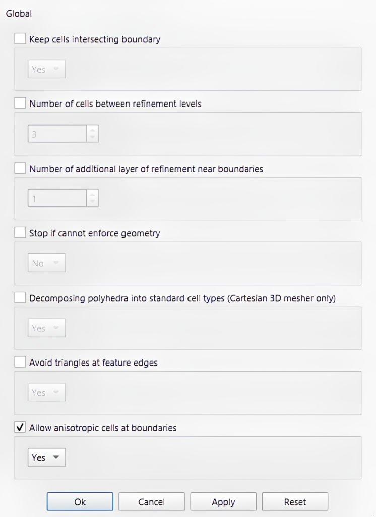
Another notable feature “Allow anisotropic cells at boundaries”, complementing the anisotropic meshing methodology, can be accessed in Settings -> Template mesh controls -> Global. “Allow anisotropic cells at boundaries” is illustrated in the picture below. It should be used with caution and only employed when the anisotropic cells are aligned with the boundary. In our example, the template aligns seamlessly with the boundary where anisotropic cells will be located, making it appropriate to activate this option.
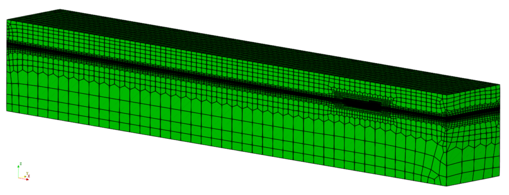
Mesh overview
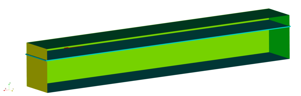
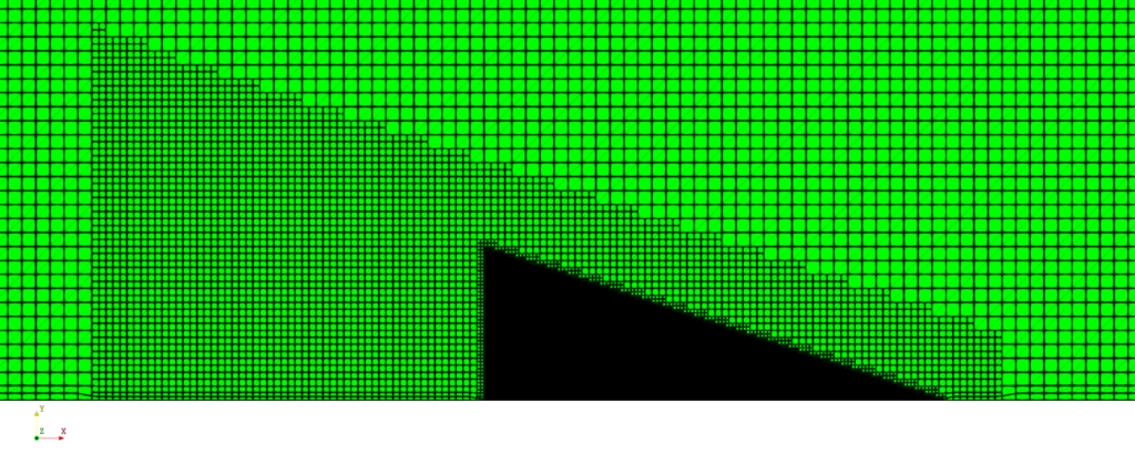
The final mesh consists of 1229321 cells, with 8 boundary layers around the hull. It accurately captures our geometry and includes refinements in parts of the calculation domain where needed. As depicted in the image of the entire domain below, the resulting mesh exhibits refinement around the free surface in the Z direction, as previously configured. This refinement decreases the required number of cells for this simulation type, resulting in substantial time savings for engineers.
The boundary layer generation algorithm enables a robust and consistent tool for obtaining the desired y+ value at a different location within the computational domain without sacrificing the smooth transition from boundary layer cells to larger free stream cells despite a larger number of layers. The available options allow you to fully control the parameters of the boundary layers and you can easily tailor the grid to your specific needs.
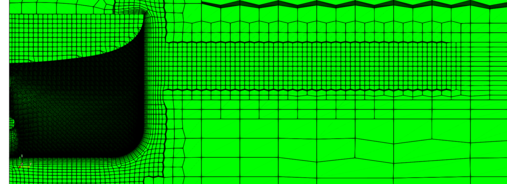
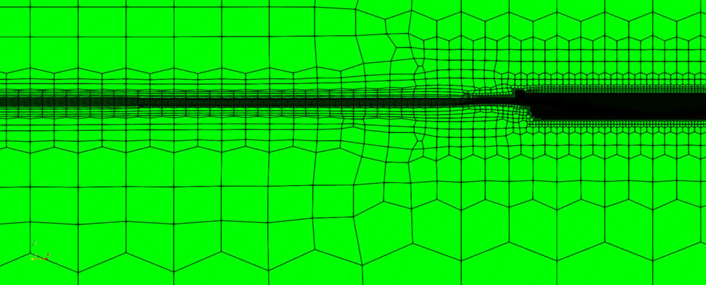
In the picture below, you can observe the effects of the additional refinements configured in the previous chapter.
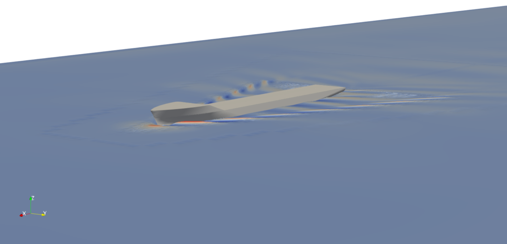
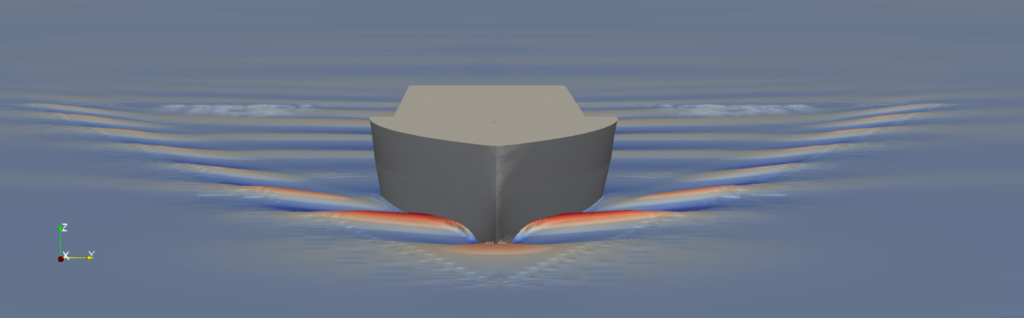
Simulation results
For the KCS hull analysis, we used interFoam solver available in OpenFOAM-v2206. The simulation results are depicted in the picture below.
If you wish to examine the meshing and simulation setup in detail, you can find this case in our download examples.
I hope that you have found this post useful and that it has made you curious to try out CF-MESH+ and its Anisotropic Mesh Refinement feature. You can also subscribe to our newsletter to stay informed on our newest developments.
- cfMesh 1.2 Released — Introducing a Full GUI for Streamlined Meshing Workflows
- How to install a trial version of CF-MESH+
- Our best meshing practices for high-quality CFD simulations
- Is it always the mesh? Part 7: Volume Ratio – the Secret Killer Nobody Talks About
- Automatic Acute Edge Detection and Fillet Creation Algorithm
")
