Introduction
The outer boundary layer is a very useful option in our boundary layer library. Mostly it is used in aerodynamic and heat transfer applications, where a fine boundary layer near the wall is desired. Its role is to provide a smooth transition between the finer inner part of the layer and the internal mesh. In the following blog post, the outer boundary layer is thoroughly explained, using a NACA series airfoil as an example. In this case, the boundary layer is generated using the Thickness ratio option and the Thickness ratio|1st layer thickness option from the Patch-based settings.
Base mesh
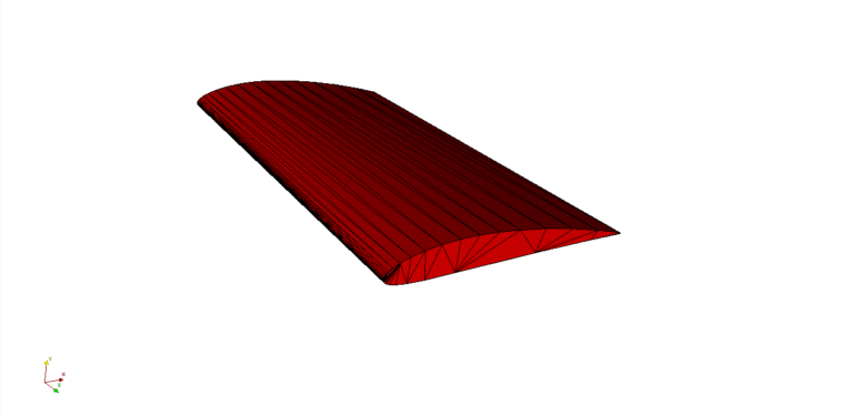
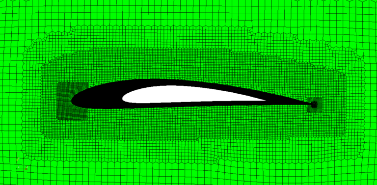
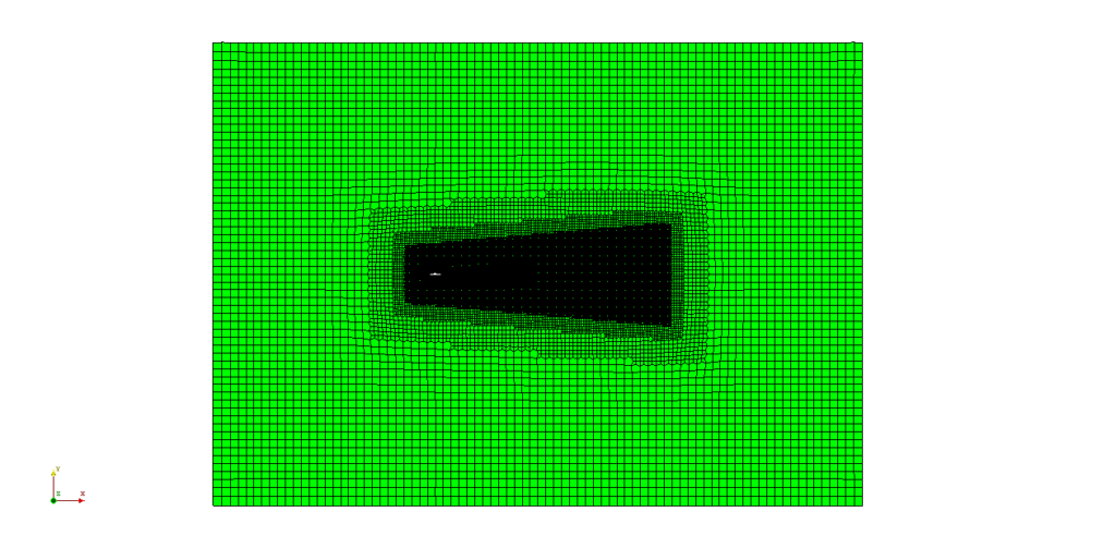
The base mesh of a NACA series airfoil without a boundary layer is given in the figures below. The mesh is refined near the leading and the trailing edges and contains a few refinement regions around the airfoil.
Thickness ratio
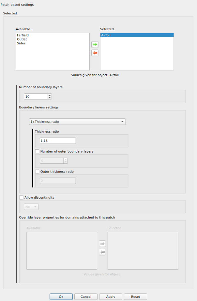
In the first example, the boundary layer is generated with the Thickness ratio option and without the outer boundary layer. This is the most robust option, with the least number of constraints. Therefore, the convergence rate of the boundary layer refinement algorithm will be the highest of all the options. However, control of the first layer thickness is not possible. In this option, only the number of boundary layers and the thickness ratio have to be provided. In the first example, the boundary layer consists of 10 layers with the thickness ratio set to 1.15. Settings and the constructed mesh near the leading edge are given in the figures below.
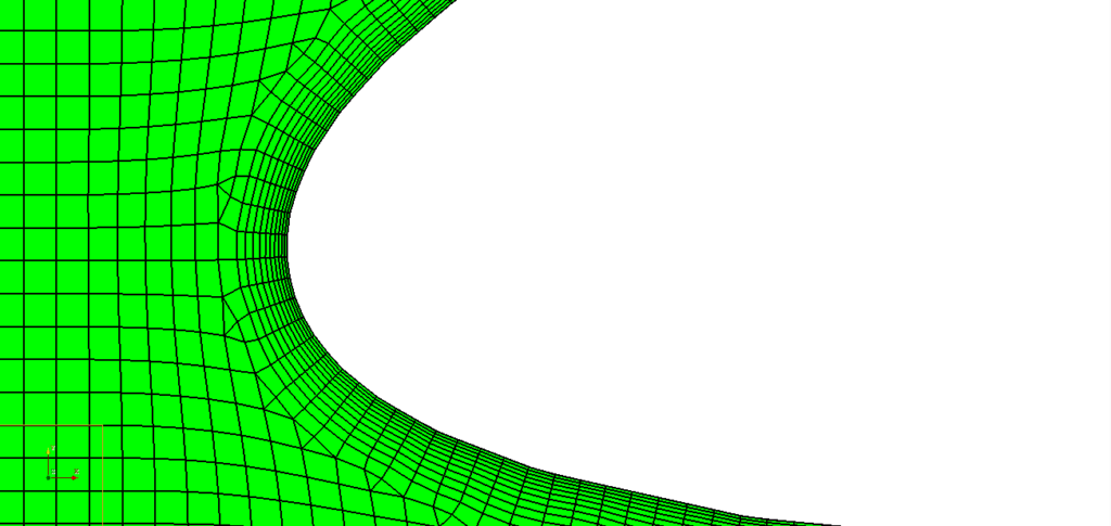
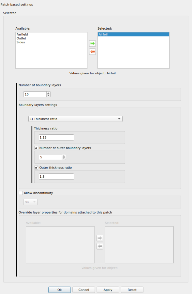
In the second example, the outer boundary layer option is enabled. In other words, the boundary layer consisting of 10 layers is separated into the outer boundary layer and the inner boundary layer. The number of outer boundary layers is set to 5 and the outer thickness ratio is set to 1,5. The number of layers in the inner part is the difference between the overall number of layers and layers in the outer part, which is equal to 5.
Thickness ratio|1st layer thickness
The first layer thickness option is a replacement for the max first layer thickness that was available in previous versions. It is also the preferred option when a fine boundary layer is desired. Here the outer boundary layer is enabled by default. However, it is only possible to set the number of outer boundary layers, and not the outer thickness ratio.
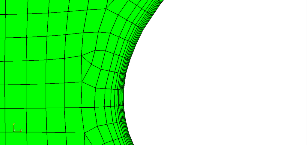
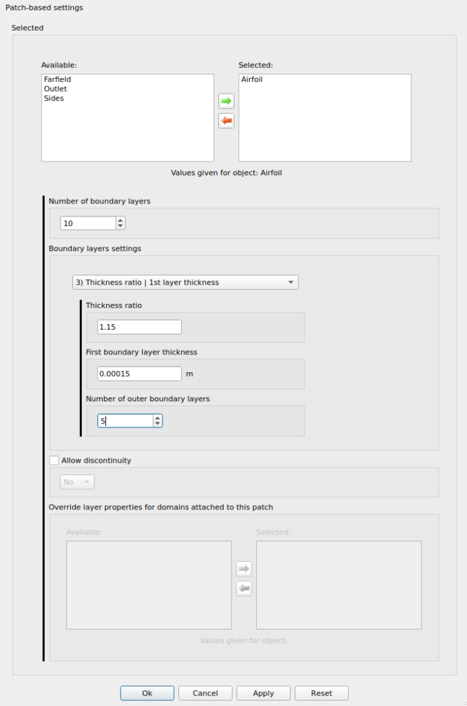
The newly implemented algorithm ensures the best possible outer thickness ratio so that the transition between the inner part of the layer and the internal mesh is as smooth as possible. When an extremely small value of y+ is desired, there can be a difference of several orders of magnitudes between the first few cells near the wall, and the cells in the internal mesh. Therefore, the outer layer must smooth this transition, if possible. The thickness of the first layer is set to 0.00015, the thickness ratio to 1.15, and the number of outer layers to 5.
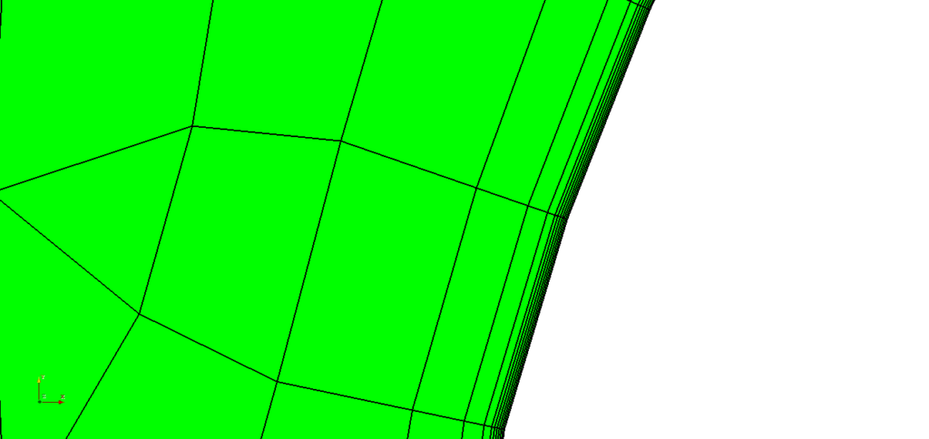
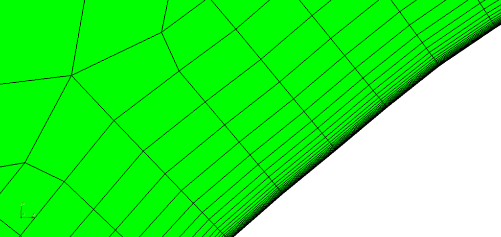
From the figures, the role of the outer boundary layer is obvious. However, one can also notice that for the chosen settings, a smooth transition is not easily achievable. Therefore, in these situations, we recommend increasing the number of layers. In this case, the overall number is increased to 20, and the number of outer layers to 10. In most cases, it is advisable to have more outer layers than inner layers. The improved mesh is shown in the figures below.
Conclusion
The concept of separating the boundary layer into the inner and the outer parts has proved to be very useful in many cases. Hope you will find our implementation convenient and easy to use, and feel free to suggest any improvements.
If this post has made you curious, feel free to try out our latest CF-MESH+, designed to alleviate the pain of meshing. You can also subscribe to our newsletter to stay informed on our newest developments.
- cfMesh 1.2 Released — Introducing a Full GUI for Streamlined Meshing Workflows
- How to install a trial version of CF-MESH+
- Our best meshing practices for high-quality CFD simulations
- Is it always the mesh? Part 7: Volume Ratio – the Secret Killer Nobody Talks About
- Automatic Acute Edge Detection and Fillet Creation Algorithm
")
