1. What are feature edges
The feature edges are surface mesh sub-elements whose existence is often very important in the meshing process – where they are treated as constraints. These are the sharp corners/edges in the domain which, when specified as feature edges, cause the software to closely capture them during the meshing process. We always highly recommend creating the feature edges before starting the meshing process.
2. Feature edge creation
The toolbar contains a set of objects displaying options/actions. One of the options is Visibility which contains Show feature edges – toggles display of feature edges.
In order to create feature edges, right-click inside the viewer window, and from the context menu press Feature edges selection/Auto-select edges and select feature with the feature angle set to 45. Press the green button to confirm.
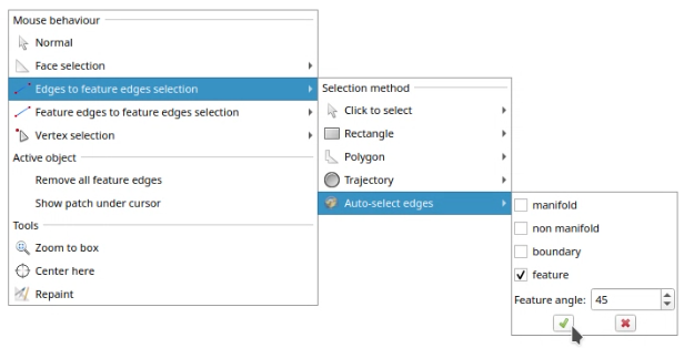
You can also use additional selection methods seen above if you think that the auto-select edges method did not catch all of the edges important for the geometry to be preserved. But the next chapter will show you that you have to be careful in doing so.
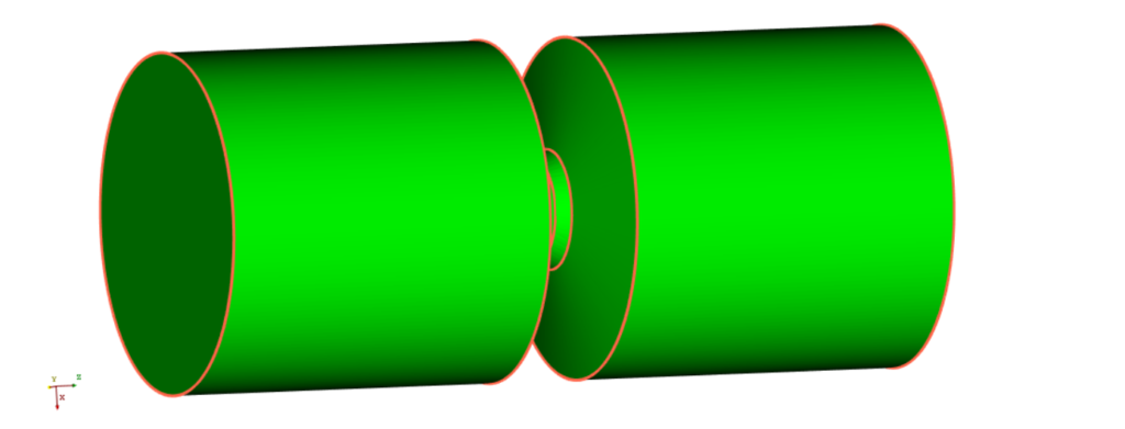
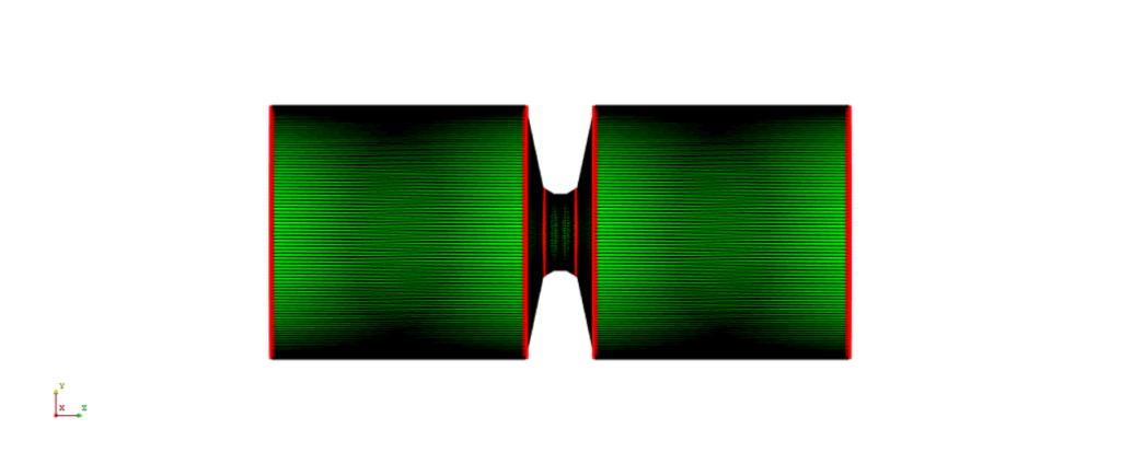
Selected edges appear e.g. for the geometry shown in the introduction:
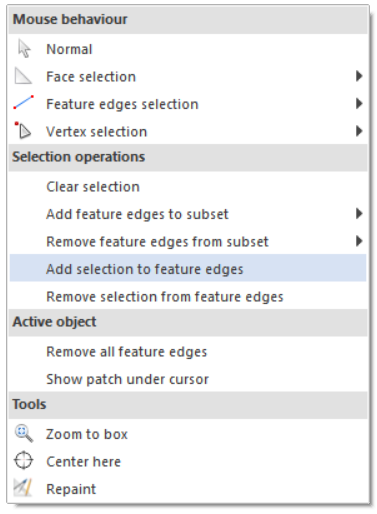
Now we have to add selected edges to feature edges by right-clicking on the geometry and from the context menu by pressing Add selection to feature edges.
3. Too many or not enough feature edges
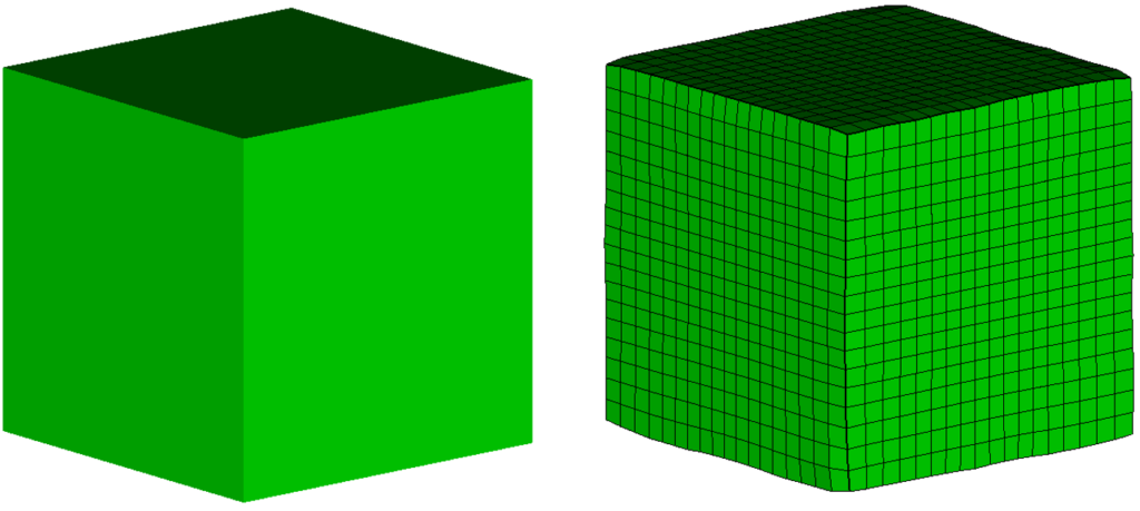
In order to emphasize the importance of correctly defined feature edges, here are two examples of a simple cube mesh without any and with too many feature edges. The geometry used in this demonstration is a simple 10x10x10 cm cube.
If we try to get a mesh without feature edges using the given geometry, the mesh gets slightly distorted at the edges as shown in the picture below:
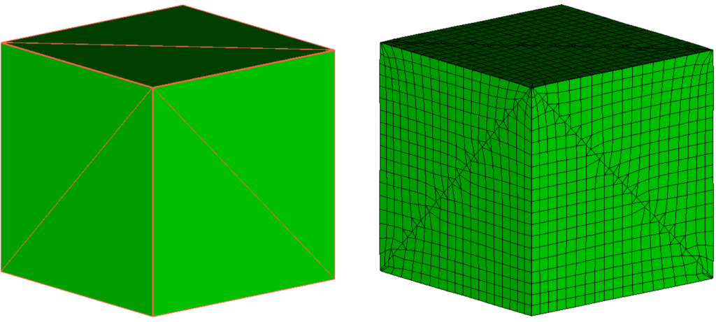
You can also define too many feature edges for a given geometry. As said in the introduction, they cause the software to closely capture them during the meshing process. So when we define edges that do not represent corners as feature edges the mesh also gets distorted in those places (which can cause bad cells in extreme cases) as shown in the pictures below:
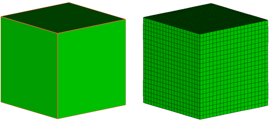
The correct way to define feature edges in a given geometry would be as shown in the picture below:
Conclusion
This report explained how to create and correctly define feature edges using CF-MESH+. It also showed the importance of the feature edges definition for the final mesh quality. Missing feature edges on sharp corners/edges of the geometry cause slight distortions on those edges, but the feature edges in places where they are not needed can also cause unwanted distortions.
I hope you have found this post useful and that it has made you curious to try out our latest CF-MESH+, designed to alleviate the pain of meshing. You can also subscribe to our newsletter to stay informed on our newest developments.
- cfMesh 1.2 Released — Introducing a Full GUI for Streamlined Meshing Workflows
- How to install a trial version of CF-MESH+
- Our best meshing practices for high-quality CFD simulations
- Is it always the mesh? Part 7: Volume Ratio – the Secret Killer Nobody Talks About
- Automatic Acute Edge Detection and Fillet Creation Algorithm
")
