1 Introduction
This report explains gap handling, i.e. cell keeping/removing options embedded into cfMesh library. All cases are discretized using cartesianMesh workflow. Furthermore, all the necessary preparation steps that precede operations in cfMesh are outlined. Three test cases are introduced and the properties of cell manipulation options are shown by examples.
2 Test Cases
2.1 Connected Rectangular Vessels
The purpose of this test case is to describe the benefits of the keepCellsIntersectingBoundary option which exists within the cfMesh library. The case geometry is shown in Figure 1.
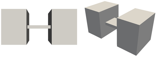
Figure 1: Front (a) and isometric (b) view of the test case geometry.
The above geometry is created using FreeCAD and exported in STEP format. This STEP file is imported into Salome under the Geometry module. Then, New Entity → Group → Create Group should be selected for the definition of patches on the domain’s boundaries. After this task is accomplished, the domain is discretized via Mesh → Create Mesh option in the Mesh module.
Since cfMesh requires triangulated surfaces, one should select 2D in the Create mesh window with Netgen 1D-2D as the algorithm while Hypothesis is left as default. In Object Browser now exists Mesh. The right mouse click on the highlighted created mesh (below Algorithms in the project tree), and the execution of the Compute option results in triangulated surfaces. With Mesh → Create Group option is needed to pass the patches on these triangulated surfaces. There one should activate Face as Elements Type with Groups on geometry in Group type. Each patch is taken into account with Direct geometry selection under the Geometrical Object option. The name written in the Name field is one that will exist in the final mesh file. During this study, the name in the project tree differed from the specified name and it was needed to correct it manually.
The last step is to load the salomeTriSurf.py script located in cfMesh source code (cfMesh/python/Salome) via File → Load Script. Finally, execution of triSurf().writeFms(“meshName.fms”), while the mesh is marked in Object Browser, creates an fms file in the directory that contains the Salome installation.
On the obtained mesh, here named twoVolumes.fms, one should generate feature edges with surfaceFeatureEdges utility as shown in Listing 1.
Listing 1 Generating feature edges in the mesh
1: surfaceFeatureEdges -angle 10 twoVolumes.fms twoVolumesEdge.fms
The settings specified in the meshDict file are given in Listing 2.
Listing 2 meshDict file for the initial mesh
1: surfaceFile “twoVolumesEdge.fms”;
2:
3: maxCellSize 0.005;
From the obtained mesh (Figure 2) one can notice that only one volume exists.
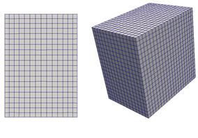
Figure 2: Front (a) and isometric (b) view of the obtained mesh without using the keepCellsIntersectingBoundary option.
By default, cfMesh works only with those cells that are completely settled inside the mesh template. Since the cells in the thin region intersect the mesh template boundaries, they are not part of the initial mesh template (Figure 3) and therefore are neglected in the further steps of the mesh generation process.
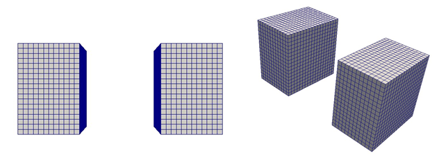
Figure 3: Front (a) and isometric (b) view of the mesh template for the case in Figure 2.
Furthermore, cfMesh performs mesh generation in a single domain. If parts are detached, then the part with most cells is kept. In the present case, two detached parts have the same number of cells, and one whose patches first appear in fms file (left volume in Figure 3a) is retained (Figures 2 and 4a). Introducing local refinement at the right side of the right volume (outlet patch) ensures the preservation of that volume because this volume now contains the highest number of cells.
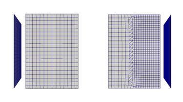
Figure 4: Left volume (a) is kept because its patches appear first in the fms file while the number of cells in both volumes is the same. This can be checked by visualizing the inlet patch. Right volume (b) is kept due to the highest number of cells. One can check whether is this the right volume by visualizing the outlet patch as shown.
Introducing keepCellsIntersectingBoundary within meshDict file as shown in Listing 3, makes dicretization of the whole domain possible (Figure 5).
Listing 3 meshDict file for the final mesh
1: surfaceFile “twoVolumesEdge.fms”;
2:
3: maxCellSize 0.005;
4:
5: keepCellsIntersectingBoundary 1;
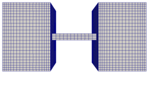
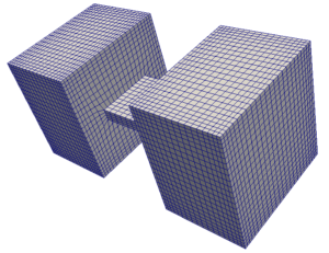
Figure 5: Front (a) and isometric (b) view of the obtained mesh with the applied keepCellsIntersectingBoundary option.
2.2 An Obstacle in the Flow
Within this case, an obstacle exists in the flow domain as shown in Figure 6.
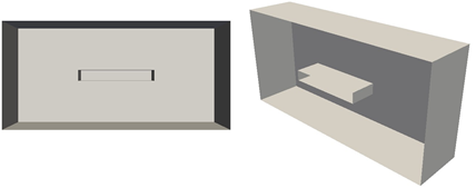
Figure 6: Cross-sectional view of the present case geometry.
The geometry preparation step is the same as in the last section with a small difference while marking the patches in Salome. Since the obstacle exists inside the volume, the Clipping option has to be applied for the selection of the obstacle patches.
For this case, the keepCellsIntersectingPatches option is not necessary. It could be neglected or defined as inactive as shown in Listing 4.
Listing 4 meshDict file for the mesh with an obstacle
1: surfaceFile “gapInFlowWithEdges.fms”;
2:
3: maxCellSize 0.005;
4:
5: keepCellsIntersectingBoundary 0;
The resulting mesh is shown in Figure 7.
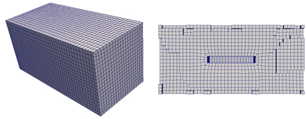
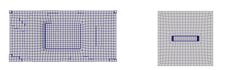
Figure 7: Discretized domain with the obstacle (a) and its cross-sectional views (b-d).
On the other hand, if the keepCellsIntersectingBoundary is switched on, the obstacle would not exist in the final mesh as depicted in Figure 8.
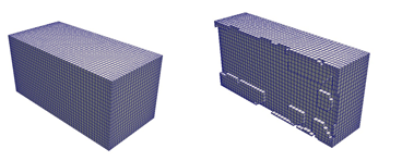
Figure 8: If keepCellsIntersectingBoundary is applied the obstacle is neglected and the whole domain is meshed.
2.3 A Wide Obstacle in the Flow
The purpose of this case is to deal with a combination of the previous two situations. In Figure 9 one can recognize the gap and thin passages on the right and left side of the obstacle. The preparation step is the same as in the previous section.
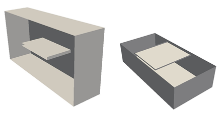
Figure 9: Cross-sectional view of the domain with the wide obstacle.
Specifying the global keepCellsIntersectingBoundary option like in the previous case would not generate the acceptable mesh (Figure 10). To ensure the preservation of cells in specific regions, cfMesh has the keepCellsIntersectingPatches option.
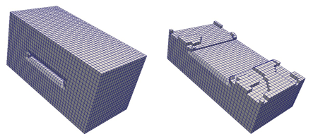
Figure 10: The mesh treated only with the global cell removing option.
Local cell preservation is done utilizing the aforementioned keepCellsIntersectingPatches option as given in Listing 5. The patch outerWalls refers to the front, back, above, and bottom side of the domain (Figure 11a).
Listing 5 meshDict file for the case of wide obstacle in the flow
1: surfaceFile “wideGapInFlowEdges.fms”;
2:
3: maxCellSize 0.005;
4:
5: keepCellsIntersectingBoundary 0;
6:
7: keepCellsIntersectingPatches
8: {
9: outerWalls
10: {
11: keepCells 1;
12: }
13: }
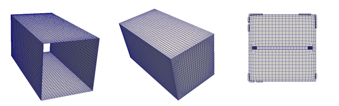
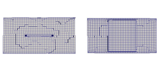
Figure 11: Specially treated patch (a), discretized domain with the wide obstacle (b) and its cross-sectional views (c-e).
3 Conclusion – gap handling in cfMesh
This report explained cell manipulation options contained within cfMesh library. Three test cases were built and the properties of cell manipulation options were shown. All the final meshes satisfy the mesh quality criteria inspected by the checkMesh utility.
If you have any cfMesh-related questions, feel free to join our cfMesh group on Facebook.
By Alen Cukrov
")
