Quite often I hear complaints about skewness, and how it’s worthless even trying to run a solver on a mesh etc.
The point of this series of posts is to give you an overview of the popular myths and to help you understand what’s going on in your Finite-Volume CFD code and how to interpret mesh quality checks for your particular problem. The goal of this post is to demystify skewness and its impact on accuracy.
Skewness – definition
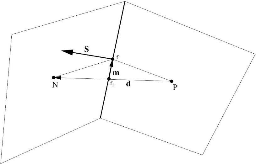
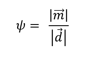
Skewness is measured as the relative distance between the face centre and the point where the line connecting the neighbouring centres of a face intersects the face and the distance between the neighbouring cell centres. You can also read more in our previous post. Skewness does not affect the validity of a mesh. However, lower values are desired!
Interpolation schemes
The accuracy of divergence, gradient and convection terms is mostly influenced by the choice of the interpolation scheme from cell centres to face centres. To keep the analysis short and informative, the focus will be on two schemes namely, linear interpolation (also called Central Differencing) and the upwind interpolation scheme. Most other schemes are a blend of this scheme, designed to achieve accurate solutions without the unphysical oscillations that may occur when using the linear interpolation scheme.
Linear interpolation (CD) is a natural second-order interpolation practice:
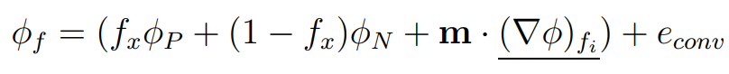
The truncation error for the scheme has the form:
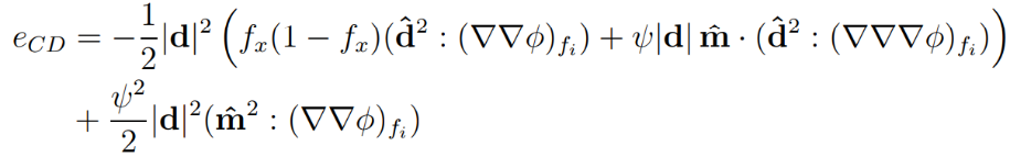
And it reveals that:
- The error is zero for solutions with the second gradient equal to zero.
- It is second-order accurate because the |d|, depending on the cell size is of the power of two.
- Skewness influences the accuracy and the lower values of skewness are beneficial.
- Uniformity fx also influences the accuracy, and it is smallest when the mesh is uniform fx=0.5;
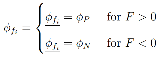
Upwind differencing (UD) is a first-order interpolation practice introduced to ensure boundedness.
Its truncation error is:
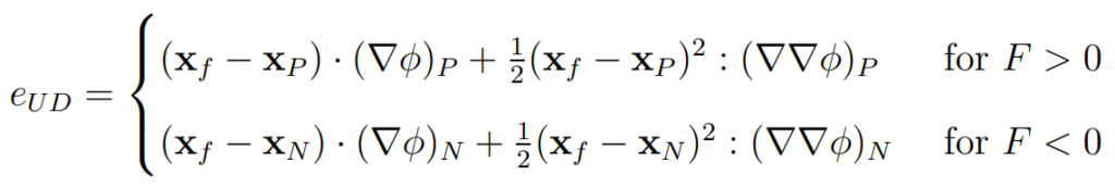
This truncation error shows that:
- Skewness and uniformity are not relevant quality metrics when upwind interpolation is used.
- The scheme is diffusive and first-order accurate. The leading term depending on the cell size is (xf – xP).
- The error is zero only for solutions with zero gradients (constant value).
Truncation errors
In the previous post, available here, it was already mentioned that skewness is a quality measure relevant for convection, gradient and divergence terms.
Let us start by looking into the truncation error for the above-mentioned terms. It does not tell anything about the exact error in the solution, it is of great help in understanding how various parameters influence accuracy.
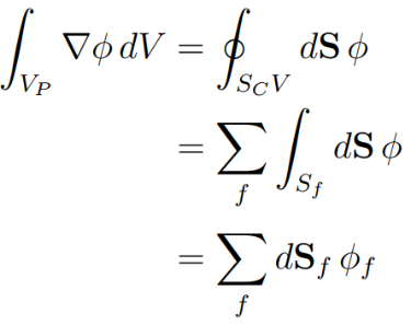
Gauss gradient
This scheme calculates the gradient from the sum of the interpolated values at the face centres of a cell:
When the gradient is approximated using the Gauss scheme and using linear interpolation, the truncation error has the form:
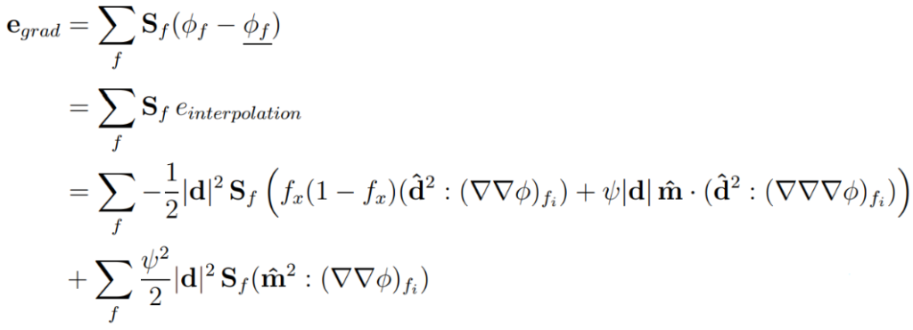
The conclusions that can be drawn from the equation above:
- The gradient term is second-order accurate because all |d| terms depending on mesh size reduce with the power of two when the mesh is refined.
- Skewness influences accuracy only when the second gradients of the solution are not zero. In short, where the solution is uniform, skewness does not affect the accuracy of the solution.
- Uniformity fx influences the accuracy of the interpolated values at a face and is minimal when the mesh is uniform fx = 0.5 (the face centre is in the middle between the cell centres).
- In boundary layers, skewness is usually important at feature edges with acute angles, such as leading and/or trailing edges. This is best resolved by modifying the geometry with fillets or chamfers, you can read more about it in this post. Another solution is to create a lot of thin layers to minimise the influence of small faces where the skewness is important on the error, by minimizing Sf terms at skewed faces.
- The error depends on the number of faces in the cell. The cell type has an influence on the accuracy.
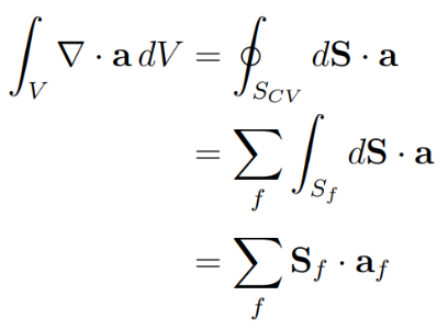
Divergence
These terms are approximated as a sum of face integrals and by using the linear interpolation:
And their truncation error has the form:
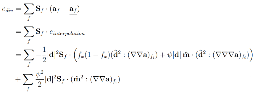
By comparing the truncation error for the divergence term with the truncation error for the Gauss gradient, the only noticeable difference is the dot product operator compared to the standard multiplication operator for the gradient term. Hence, the same conclusions can be drawn as in the case of the gradient term.
Convection term
The convection term is often the largest source of discretisation errors in the solution, especially in the momentum equation because of its non-linear nature (the velocity is transported by itself). The accuracy is dependent on two important aspects:
- Mesh quality – the goal is to provide information on how cell size, uniformity and skewness affect accuracy.
- Interpolation scheme – numerous schemes have been developed to achieve an accurate solution and avoid unphysical solutions.
The approximation of the convection term is performed as a sum over faces:
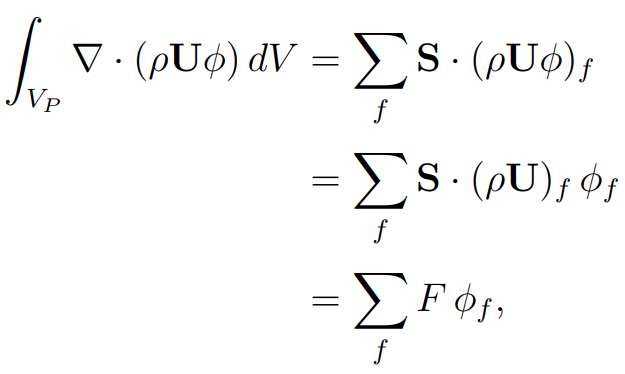
Where F is a mass flux through a face:
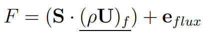
and \phif is the interpolated value at a face. The error in the convection term is influenced by the error in the flux and the interpolation at face, and this can be written as:
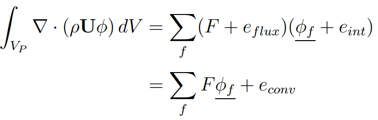
Where the error term can be further re-arranged:
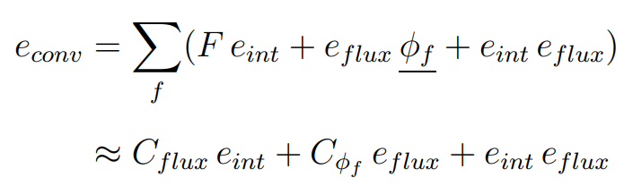
The discretisation error is dependent on:
- The type of cell used.
- Interpolation scheme.
- The scheme for the calculation of mass fluxes if they are not available explicitly.
- Alignment of the mesh with the flow – by aligning the mesh with the flow it is possible to reduce the number of faces with non-zero mass flux that contributes to the error.
Key takeaways
The most important takeaways about skewness, which I never seem to get tired of telling our users, are:
- Skewness does not affect accuracy in regions where the solution is uniform! Avoid it in jets and other features where the higher gradients are significant.
- Skewness does not play a role when using the upwind scheme. This scheme is diffusive and is not the best choice when accurate solutions are desired.
- The influence of skewness on the calculation of the gradient terms can be reduced by paying attention to the input geometry used for meshing, as described in one of our previous posts.
I hope that you have found this post useful and that it has made you curious to try out our latest CF-MESH+, designed to alleviate the pain of meshing. You can also subscribe to our newsletter to stay informed on our newest developments.
- cfMesh 1.2 Released — Introducing a Full GUI for Streamlined Meshing Workflows
- How to install a trial version of CF-MESH+
- Our best meshing practices for high-quality CFD simulations
- Is it always the mesh? Part 7: Volume Ratio – the Secret Killer Nobody Talks About
- Automatic Acute Edge Detection and Fillet Creation Algorithm
")
