Quite often I hear complaints about non-orthogonality, the required number of non-orthogonality correctors to achieve convergence, and how it is worthless even trying to run a solver on a mesh, etc. The point of this series of posts is to give you an overview on the popular myths and to help you understand what is going on in your Finite-Volume CFD code and how to interpret mesh quality checks for your problem. The goal of this post is to de-mystify the impact of feature edges and corners on accuracy and discuss real-world geometries and their impact on accuracy, too.
Sailing on a ferry from Split to the beautiful island of Vis in Croatia, by walking on a deck I started observing various parts and started thinking how feature edges do not exist anywhere. They are mostly used in the modeling world, with a goal to use less cells and save on computational resources. As everything has its pros and cons let us discuss them and how this affects the physics in the CFD solution.
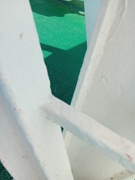
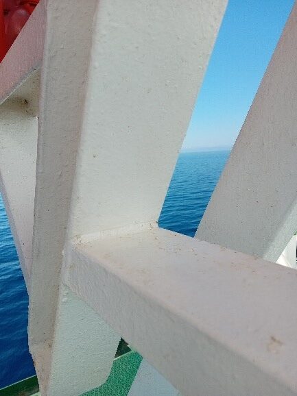
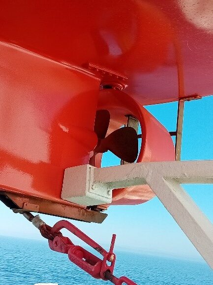
Sharp edges do not exist in the real world
Treating highly-curved parts of the geometry as sharp edges helps in reducing the number of cells in the mesh. Highly-curved parts require very small cells, at least two cells across the radius that can become a huge burden in some cases when the computational resources or deadlines are tight.
Feature edges and corners are absolutely needed for modeling inlets/outlets, symmetry planes, wedges, etc. as they represent an arbitrary position in the overall operating domain. In addition, an intersecting layer topology is needed there to achieve better accuracy of gradients in the boundary layer.
Acute angles at feature edges inside the domain are extremely challenging for the meshing process and they shall be avoided at all costs. Let me elaborate on what kind of problems they cause and how to avoid such problems:
- By approaching an acute feature edge, the cell size shall be smaller and smaller to ensure that it nicely fits the mesh to the geometry without distorting the mesh too much. A good rule of thumb that serves quite well here is: If the angle is smaller than 150 degrees it is fine to keep the feature edge. Otherwise, it is much better to create a fillet there. Please check our previous post for more information (5 Tips And Tricks For A High Quality Meshing Process).
- They are most often locations of high mesh skewness, and this is not beneficial for the accuracy of the gradient terms. This may also cause convergence problems if the gradients are not limited to their physical values.
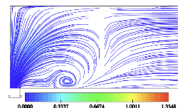
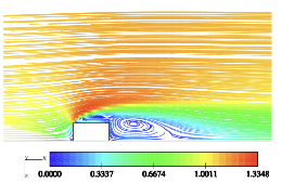
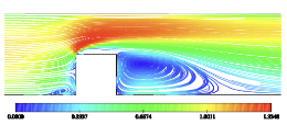
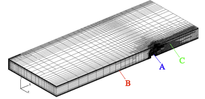
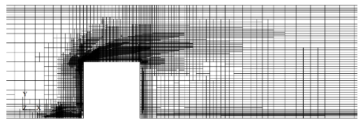
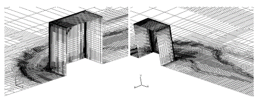
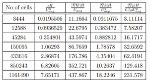
- There are also locations where the solution gradients tend to infinity with mesh refinement and hinder you from conducting a mesh-independence study. It also prevents error-driven mesh refinement from terminating because the estimated errors increase near the feature edges and cause more refinement, see the figures below representing the turbulent flow over a wall-mounted cube. As expected, the mesh needs to be fine in the boundary layer and the vortices near the cube. However, the refinement process never terminated near the feature edges of the cube and the gradients increased more and more with mesh refinement, without a sign of convergence to a single value.
Feature edges, detected as artifacts of low-quality input geometry, are the worst enemy in achieving a smooth meshing and CFD experience. They make the mesher conform to the non-existing features at the cost of reducing mesh quality, where it is not necessary. This also does not help the solver converge quickly and generate accurate results. Fortunately, these kinds of problems are by far the easiest to solve, by using our CAD-to-surface triangulation interface, capturing only the feature edges existing in the original CAD data.
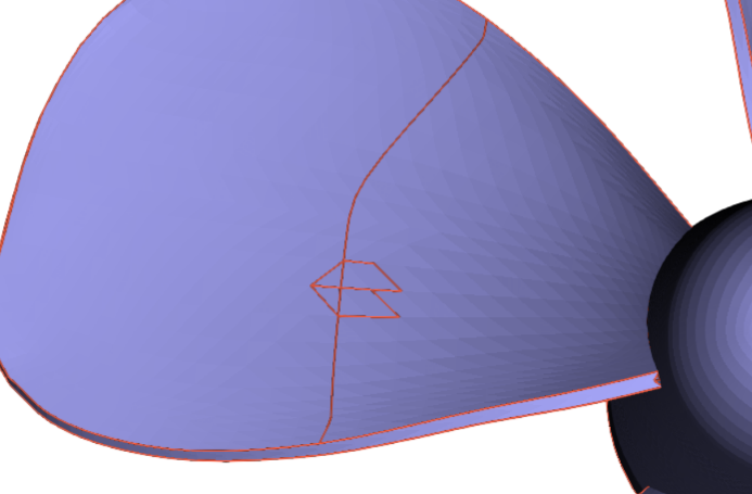
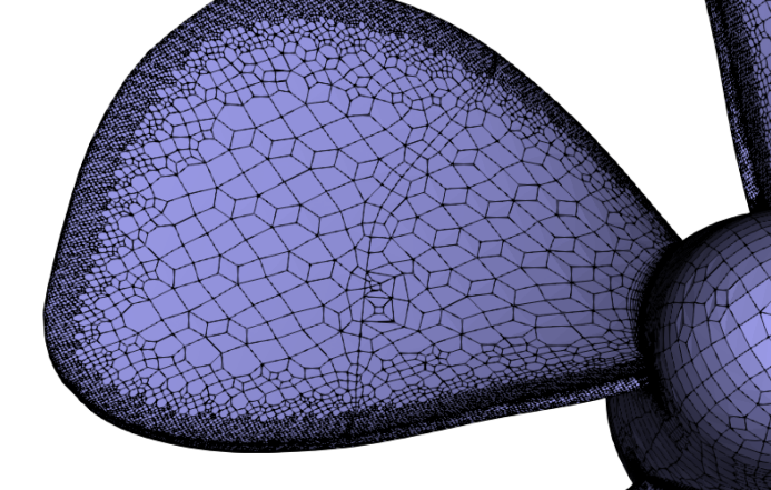
Propeller blade with unnecessary feature edges and the resulting volume mesh. The quality would be better if the edges were not there.
Key takeaways about feature edges and corners
The most important takeaways about feature edges are:
- Avoid them where they are not absolutely needed.
- Generate fillets instead of having acute feature edges.
- Use CAD to triangulation interface to avoid detecting feature edges that are artifact of low-quality surface triangulation.
I hope that you have found this post useful and that it has made curious to use the knowledge presented in this post and to try out our latest CF-MESH+, designed to alleviate you from the pain of meshing. Feel free to subscribe to our newsletter to follow the latest news in CFD meshing techniques.
- How to install a trial version of CF-MESH+
- Our best meshing practices for high-quality CFD simulations
- Is it always the mesh? Part 7: Volume Ratio – the Secret Killer Nobody Talks About
- Automatic Acute Edge Detection and Fillet Creation Algorithm
- Join us at the upcoming webinar “Next-Gen Meshing Technology at IANUS” with CF-MESH+
")
