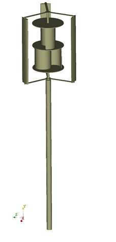
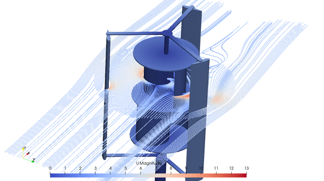
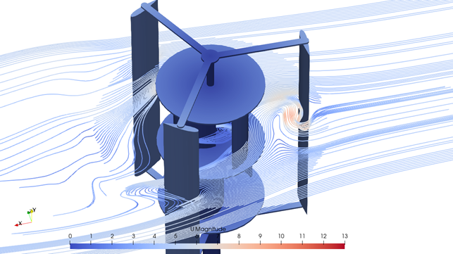
This case study demonstrates how to mesh and set up a multi-domain case with a rotating mesh. The analyzed geometry represents a Darrieus-Savonius wind turbine.
Geometry preparation
For more detailed tips and tricks on how to prepare your geometry and provide meaningful settings, please read the previous blog posts.
A vertical-axis wind turbine is a relatively simple geometry to mesh using the CF-MESH+, but some important factors should be considered before uploading the surface mesh.
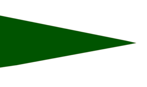
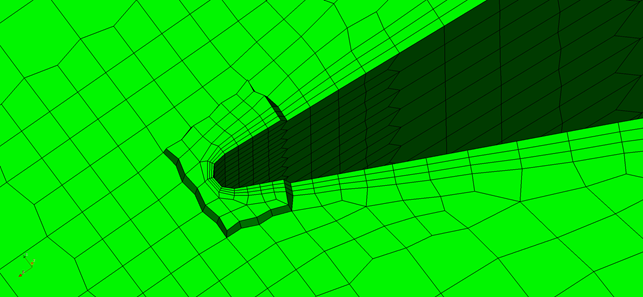
The shape of the blade’s trailing edge is crucial for the mesher to work properly. Geometries that have a sharp trailing edge (one that ends as a single vertex in 2D or as a single edge in 3D), as shown in Figure 1, should be avoided. Besides making it harder to generate a high-quality mesh with a high-quality boundary layer over the sharp edge, this type of geometry does not represent the actual shape of any mechanical part as it cannot be produced/made in the real world.
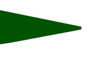
Trailing edges should be shaped with a blunt or rounded end as seen in Figure 2 and Figure 3.
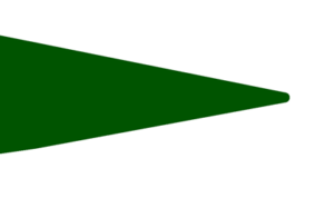
In this case, the uploaded surface mesh has rounded trailing edges.
Meshing process
The process of creating a rotating mesh in CF-MESH+ starts by creating two different cylinder primitives around the imported surface mesh. The primary role of the bigger outer cylinder is to define the fluid domain around the wind turbine. The smaller inner cylinder determines the rotating domain.
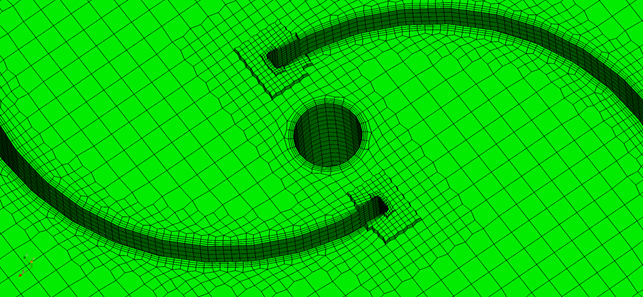
The next step is defining the patches (boundaries). In this case, there are four different patches: outerZone, innerZone, ground, and turbine. Patch outerZone belongs to the outer cylinder, innerZone belongs to the inner cylinder, while patch ground is shared between the two cylinders. The surface mesh of the wind turbine belongs to the patch turbine.
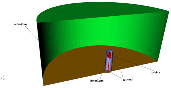
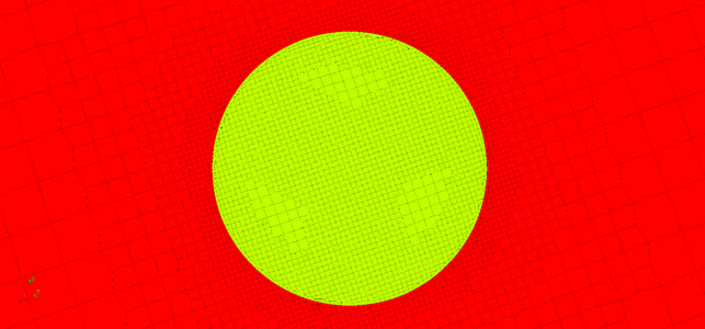
In order to create a rotating domain, the multi-domain capability in CF-MESH+ was used by activating the meshing of multiple domains in the Settings tree. The mesher sees every enclosed geometry as a potential meshing domain and it is necessary to define the domains we want to mesh. Domain definition was carried out by specifying the patches unique to a given domain. The user must be aware that the combination of patches used to define a domain must be strictly unique to the given domain. Patches innerZone and turbine were selected for defining the rotating domain named rotatingDomain, while patch outerZone was selected for defining the domain named fixedDomain.
To create a sliding interface, it was necessary to enable the Detach points at the internal interfaces option in CF-MESH+. This option created two patches named innerZone_fixedDomain and innerZone_rotatingDomain at the interface of the domains, later used for defining coupling conditions at the interface.
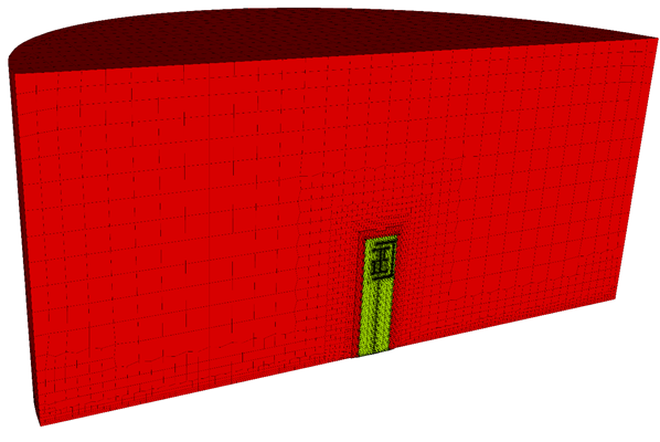
The next step is choosing the appropriate cell sizes over the domain. Although the wind turbine has a diameter of 0.6 m, the maximum cell size of 0.4 m was set in the master settings. This was done to reduce the number of cells in the domain and to create a coarse mesh far enough from the wind turbine. The maximum cell size set in the master settings can be further refined in regions where the mesh resolution is insufficient. This can be done automatically or by manually selecting patches and creating face and edge subsets where refinement is needed. The region of the wind turbine, especially the blades and the hub, was refined until the cell size was smaller than the feature size. This can be easily visualized with the help of the Show cell size tool.
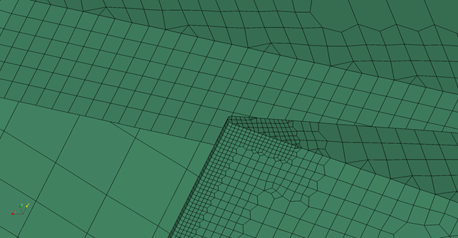
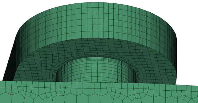
For obtaining the accurate fluid behavior around the wind turbine, it is necessary to use several layers of boundary layer cells in the areas where significant gradients are expected. Depending on the required accuracy of the solution, the low Reynolds or high Reynolds turbulence model approach should be chosen. In this case, we opted for the latter and used three boundary layers on the whole surface of the wind turbine.
Simulation setup
For the simulation of airflow around the vertical axis wind turbine, the solver pimpleFoam available in OpenFOAM-v2206 was used. The curved surface of the cylindrical domain was used as the inletOutlet patch with the airflow velocity set as (5 0 0). The time step was set as adjustable to the maximum Courant number of 1. To establish mesh motion, it was necessary to create a dynamicMeshDict in file constant, where the axis of rotation and angular velocity of the rotating domain were defined. Angular velocity was set to 12 rad/s. Arbitrary Mesh Interface (AMI) method was used for coupling conditions between patches at internal interfaces. AMI requires changes in file boundary where the boundary type of patches innerZone_fixedDomain and innerZone_rotatingDomain was set to cyclicAMI.
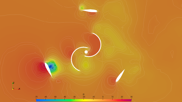
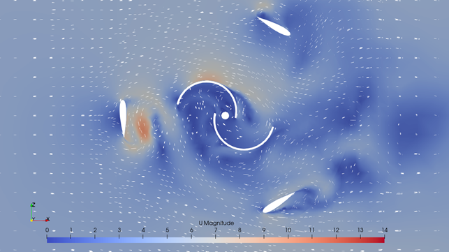
Figures 12 and 13 show the pressure and velocity field in the domain around the wind turbine.
Conclusion
This study presents the process of preparing a mesh and the solver setup, of a multi-domain case with a rotating mesh, a high-quality boundary layer mesh, and 100% layer coverage even for complex geometries, with the minimum user input. CF-MESH+ creates subsets on both sides of the rotating interface, thus simplifying the solver setup later on. Furthermore, it offers numerous options to specify refinement. Once the setup is created, the meshing is done automatically, using all available cores on your computer to speed up the meshing process.
We hope that you have found this post useful and that it has made you curious to try out our latest CF-MESH+, designed to alleviate the pain of meshing. You can also subscribe to our newsletter to stay informed on our newest developments.
By Mislav Babić and dr.sc. Franjo Juretić
- cfMesh 1.2 Released — Introducing a Full GUI for Streamlined Meshing Workflows
- How to install a trial version of CF-MESH+
- Our best meshing practices for high-quality CFD simulations
- Is it always the mesh? Part 7: Volume Ratio – the Secret Killer Nobody Talks About
- Automatic Acute Edge Detection and Fillet Creation Algorithm
")
