Introduction
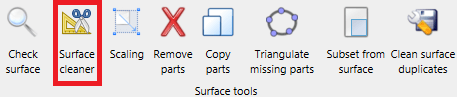
CFD engineers often have to work with geometries that were not created by professionals in the field. This situation then results in the handling of imperfect geometries, presenting challenges in the simulation process. The most common problems occurring in surface meshes are unresolved self-intersections and overlaps. To clean these problems, CF-MESH+ now offers a new utility, “Surface Cleaner”. Guided by a user-defined relative and angle tolerance, this algorithm handles overlaps and intersections, simplifying the surface mesh for improved volume mesh generation. Users now can perform a comprehensive surface mesh preparation within CF-MESH+, utilizing the tools illustrated below.
Basic surface cleaning
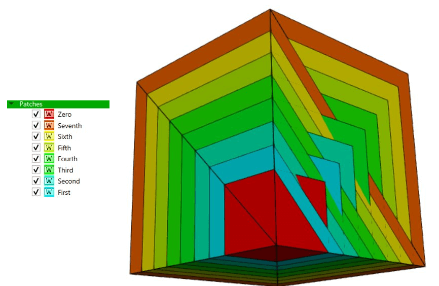
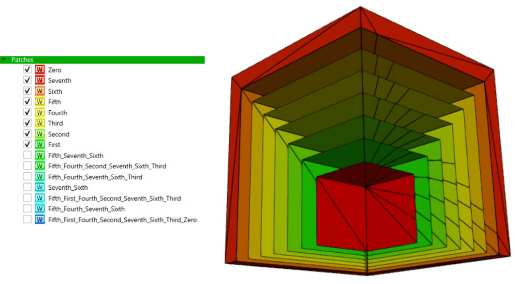
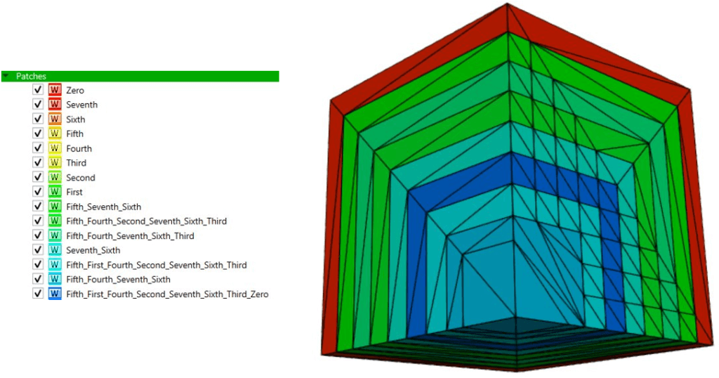
In the following example, observe the “Surface Cleaner” algorithm in action. It showcases a scenario featuring eight cubes placed inside each other, sharing a common corner. You can see how the algorithm re-triangulates the given geometry, effectively resolving these overlaps and intersections. This example highlights how the algorithm optimizes the surface, creating a more suitable configuration for the mesher and clearly defining different domains, once overlaps and intersections are resolved. The algorithm groups new triangles into a new patch and identifies all patches involved in that specific part of the surface.
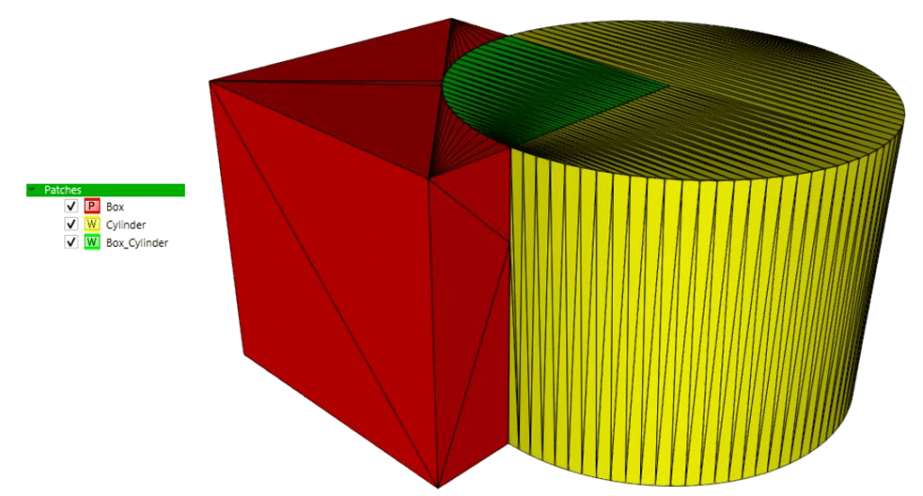
This is also demonstrated in the following example, where a cylinder intersects a cube of matching height.
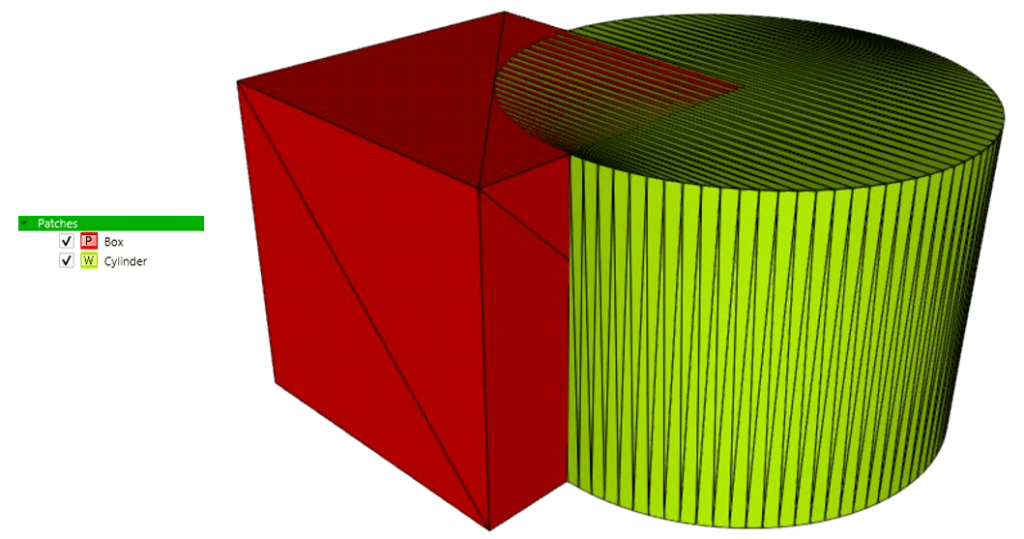
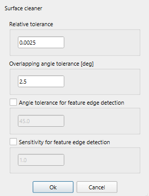
Careful selection of user-defined relative and angle tolerance is crucial when working with complex and imperfect surface meshes. Excessively large tolerance may lead to slight distortions in geometry. In cases focused on resolving intersections, a very small relative tolerance can be sufficient for the cleaner to effectively address intersection issues. The relative tolerance sets the upper limit for the distance between two points on a surface to be considered as overlapping or intersecting. This distance is determined by multiplying the average distance from a triangle’s centroid to its vertices by a user-defined relative tolerance. The angle tolerance defines the maximum acceptable angle between two triangles for them to be considered overlapping.
After the surface re-triangulation, the feature edges are re-detected. Users have the option to specify the angle tolerance or sensitivity for feature edge detection. In cases where these parameters are not specified, the algorithm defaults to using the calculated angle tolerance for feature edge detection.
Handling complex and imperfect surface meshes
To illustrate the cleanup process for a complex and imperfect surface mesh, we will utilize the HeatExchanger.fms geometry. In the unresolved geometry, most of the external components are overlapping or intersecting, while there are also internal intersecting elements not visible in the displayed image. Upon executing the ‘Surface Cleaner,’ the tool resolves overlaps and intersections, significantly improving the manageability of the surface mesh and facilitating the correct setup for volume mesh generation.
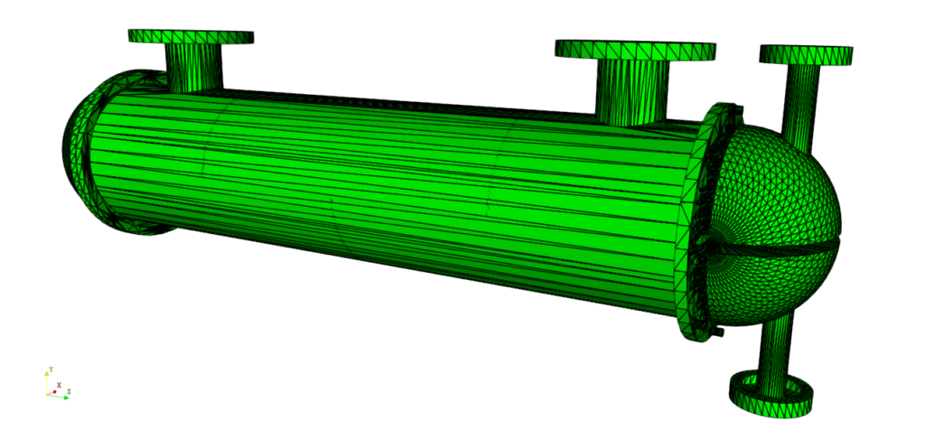
In the image above, you can observe how the ‘Surface Cleaner’ incorporates edges/triangles to merge intersecting or overlapping triangles. (Slightly lower relative tolerance than the default value, specifically 0.0005, is employed to address the shape of the unresolved triangulation. This adjustment aims to prevent distortions and ensure the effective resolution of overlaps and intersections in the surface mesh.)
Following the cleanup, you can effortlessly manipulate your mesh using the ‘Selection modes’ in the viewer and other ‘Surface tools’ like ‘Remove parts’ or ‘Triangulate missing parts.’ These tools allow you to eliminate unnecessary portions of the mesh or fill holes enclosed by specified edges.
Volume mesh generation algorithms in CF-MESH+ are fault-tolerant, as long as the defect is smaller than the required local cell size. This is especially important for multi-domain meshes, where large gaps in the geometry may cause invalid domain definitions. That’s why utilizing the ‘Surface Cleaner’ is convenient when dealing with imperfect geometries, as it helps minimize these faults.
Preparing surface meshes for MRF simulations
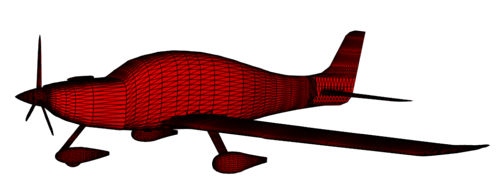
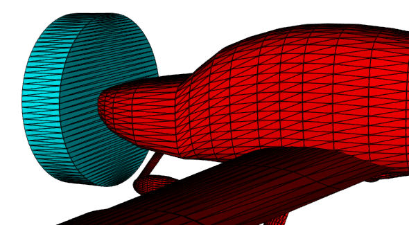
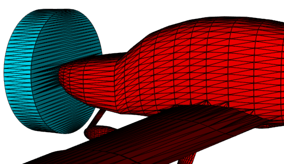
The following example will demonstrate the process of preparing the geometry of a small airplane for an MRF (Multiple Reference Frame) simulation with two domains, where one of these domains represents a rotating zone inside the CF-MESH+.
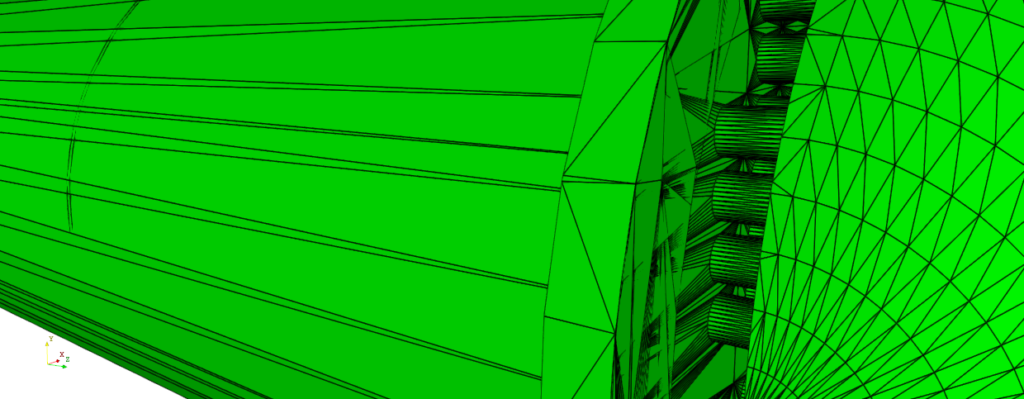
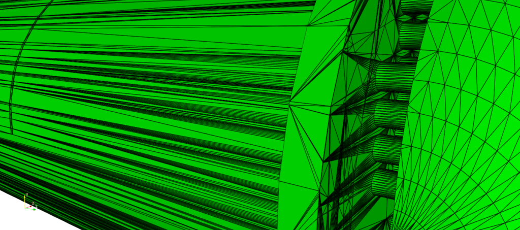
Initially, a cylinder primitive is added around the airplane blades and after that, it is merged to the surface mesh (right-click on the newly created primitive->”Merge to surface mesh”).
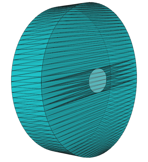
Subsequently, the “Surface Cleaner” tool is applied to define a distinct patch for the rotating MRF domain. When employing the “Surface Cleaner” for tasks like this, where we want to create separate patches by intersecting the geometry with a primitive body, it is recommended to use a very small relative tolerance (such as 0.00001 or lower). This helps preserve the geometry and prevent slight distortions during the cleaning process.
Once the cleanup is completed, the viewer selector is employed to designate an MRF interface patch, facilitating the specification of domain settings. The mesher sees every enclosed geometry as a potential meshing domain and it is necessary to define the domains we want to mesh. Using one of the available selection modes, such as “Manifold” or “Critical angle,” select the portion of the cylinder located on the outside of the aircraft patch. This selection will enable the creation of a new patch named “MRF_rotating” (right-click inside the “Viewer”->”Add faces to patch”), serving as a distinct patch for our rotating domain. Similarly, after resolving intersections, the user can easily remove parts of the surface mesh that could cause issues during the generation of the desired volume mesh (using the “Remove parts” surface tool).
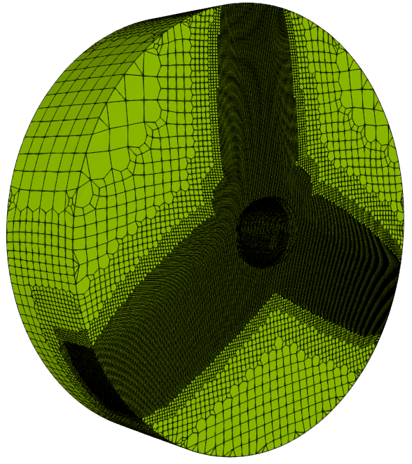
Establishing domain settings using bounding patches is now a straightforward process. Two domains need to be specified, as illustrated in the picture below. The “Bounding_box” patch in the image represents the outer mesh boundary box. The user must be aware that the combination of patches used to define a domain must be strictly unique to the given domain.
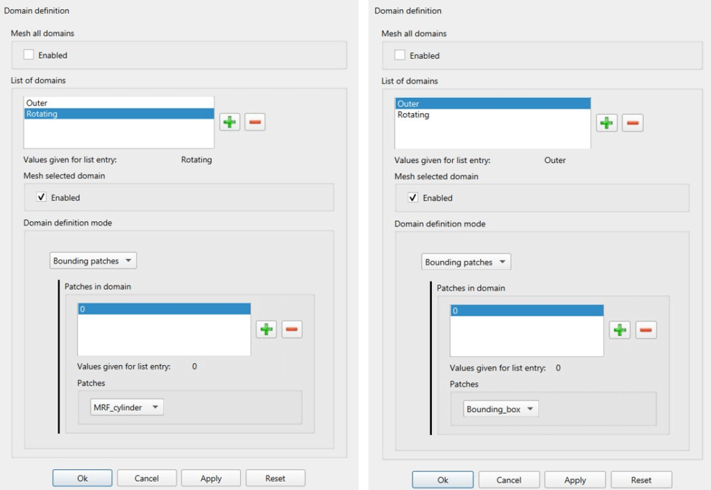
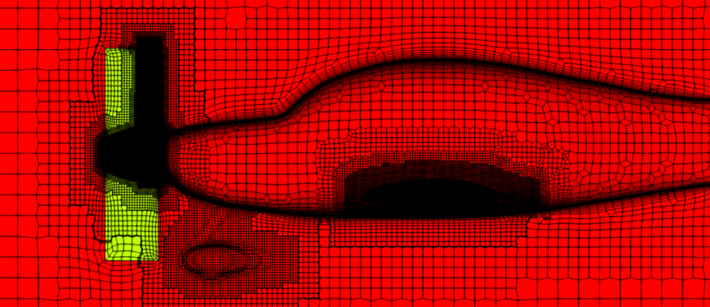
As you can see, the final mesh consists of two domains, “Rotating” and “Outer”. Such a mesh can now be utilized for MRF transient simulations.
I hope that you have found this post useful and that it has made you curious to try out CF-MESH+ and its Surface Cleaner utility. You can also subscribe to our newsletter to stay informed on our newest developments.
- cfMesh 1.2 Released — Introducing a Full GUI for Streamlined Meshing Workflows
- How to install a trial version of CF-MESH+
- Our best meshing practices for high-quality CFD simulations
- Is it always the mesh? Part 7: Volume Ratio – the Secret Killer Nobody Talks About
- Automatic Acute Edge Detection and Fillet Creation Algorithm
")
