In this report, we will show the case preparation for a CHT simulation.
Geometry preparation
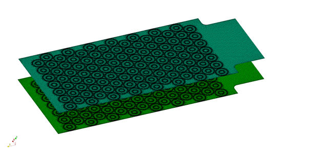
The model of the battery pack was given as a 2D drawing in a DXF file format – a vector format mostly used by engineers and architects for 2D drawings during product design. The geometry was imported to CF-MESH+ using the DXF to 2D extrusion tool located on the Tools ribbon bar. The drawing must be in the xy-plane as the extrusion is carried out only in the direction of the z-axis. The result can be seen in Figure 1.


Figure 1: 2D drawing of the battery pack (a) and extruded geometry in CF-MESH+ (b)
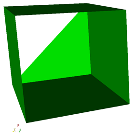
If the user wants to generate a 2D mesh using a geometry imported as an STL file, he must keep in mind that there shouldn’t be any part of geometry with a normal in the direction of the z-axis. This is because the CF-MESH+ generates 2D mesh by discretising available contours in the xy-plane, and the presence of surface triangles with the normal vector in the z-direction prevents the mesher from detecting regions inside the contour. An example of geometry suitable for 2D meshing is given in Figure 2.

Meshing process
The user experience of generating a 2D mesh in CF-MESH+ does not considerably differ from that of a 3D one. Patch assignment, domain definition, and regional refinements are the same as in a 3D case. The main difference is that there are no patches (boundaries) perpendicular to the z-axis. The mesher creates these patches after meshing.
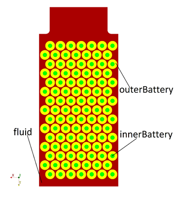
In this case, there are five different assigned patches (boundaries): inlet, outlet, casing, batteryCore, and battery.
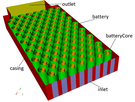
Since the purpose of the mesh was to carry out a CHT analysis, it was necessary to create multiple domains, and therefore the multi-domain capacity of CF-MESH+ was used. Three domains were created by assigning a unique set of patches for each domain. Patch batteryCore was used to define a domain named innerBattery, patch battery to define a domain named outerBattery, and patch casing to define a domain named fluid. By enabling the Convert patches at internal interfaces option, patches battery, and batteryCore were converted to face zones. This was done because when running a CHT simulation in OpenFOAM interfaces between regions are created by using the splitMeshByRegions command which does not work properly if these patches are not converted to face zones.
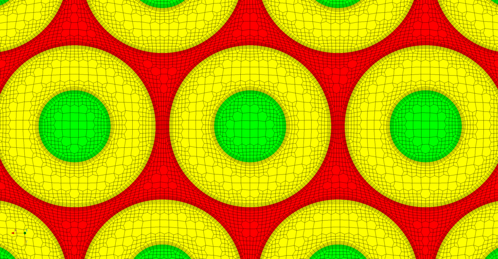
Appropriate cell sizing was set across the domain by refining the maximum cell size where necessary. Special attention was given to tight spaces between the batteries and the casing where Automatic cell sizing at selected boundaries option was used. Selecting the right refinement level can be facilitated by using the Show cell size tool.
In order to obtain accurate thermal and fluid behaviour, it was necessary to create quality boundary layers in areas where significant gradients are expected. Three boundary layer cells were generated on all boundaries between each domain.
As mentioned before, CF-MESH+ creates two additional patches named bottomEmptyFaces and topEmptyFaces after the meshing. These patches enclose the domain in the direction of the z-axis and are by default defined as empty.
Simulation setup
For the CHT simulation of air cooling the battery pack, solver chtMultiRegionSimpleFoam available in OpenFOAM-v2206 was used. Command splitMeshRegions -cellZonesOnly -overwrite was used to create one fluid and two solid regions, each with its own mesh and boundary conditions. To run the mesh as a 2D case in OpenFOAM it was necessary to set the type of every boundary condition of patches bottomEmptyFaces and topEmptyFaces to empty. Air was set to enter the domain with a velocity of 5 m/s and a temperature of 290 K. A constant heat source was defined in the fvOptions file of innerBattery region.
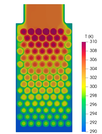
Figures 7 and 8 show the temperature and velocity field of the battery pack.

I hope that you have found this post useful and that it has made you curious to try out our latest CF-MESH+, designed to alleviate the pain of meshing. You can also subscribe to our newsletter to stay informed on our newest developments.
- cfMesh 1.2 Released — Introducing a Full GUI for Streamlined Meshing Workflows
- How to install a trial version of CF-MESH+
- Our best meshing practices for high-quality CFD simulations
- Is it always the mesh? Part 7: Volume Ratio – the Secret Killer Nobody Talks About
- Automatic Acute Edge Detection and Fillet Creation Algorithm
By Mislav Babić and dr.sc.Franjo Juretić
")
