Summary
This study presents the meshing process using CF-MESH+ developed to gain the following:
• A high-quality boundary layer mesh, needed for accurate heat transfer simulations
• 100% layer coverage even for complex geometries
• A mesh with conformal interfaces between the various mesh zones
Key Takeaways
- CF-MESH+ does not require perfect CAD data and offers utilities to clean up input geometries
- It offers numerous options to specify refinement
- Once the setup is created, the meshing is done automatically using all available cores on your computer to speed up the meshing process
The end result can be seen below, in detail.
This study presents automatic hex-dominant mesh generation of a detailed room model, carried out by using CF-MESH+. In addition, the quality of the generated mesh was tested by performing a numerical simulation of a draft flow through the room.
This study also shows the utilities available in CF-MESH+ enabling quick geometry preparation, and cell sizing setup for complex features available in this geometry. The study also shows the possibilities to refine the mesh using face subsets, enabling local mesh refinement, and are not transferred to the volume mesh. This approach enables the user to define the boundary regions in a geometry according to the boundary conditions that will be used in the simulation and use face subsets for refining the mesh. In addition, it shows high-quality boundary layers generated over the complex parts of the geometry.
Test Case
Geometry Preparation
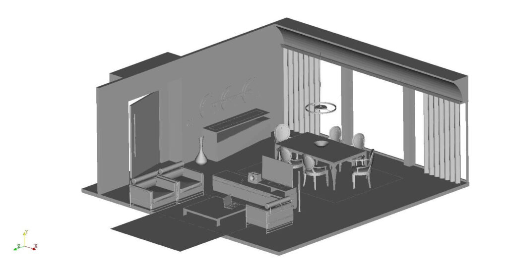
Within this study, a detailed model of a living room (Figure 1) is used. This model was created by Frederico Costa and published on GrabCAD, a digital manufacturing hub. The model is originally stored in IGS format and is converted to STL using Salome. In order to make the geometry suitable for CFD analysis, the geometry is closed. This is done as follows:
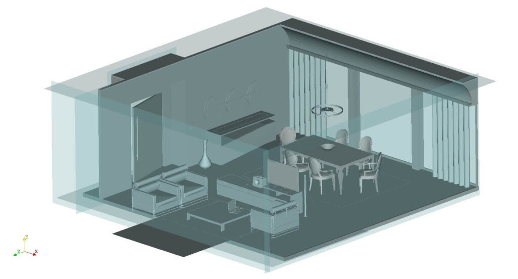
- A planar face is created in Salome and exported in STL format.
- The created planar face is imported several times in Meshmixer to obtain enough faces for closing the domain.
- Each of the faces is adopted and associated to the domain as shown in Figure 2.
- The associated parts are merged to the geometry using Paraview and exported in binary STL format.
The computational domain does not require to be watertight and therefore it is ready for volume mesh generation. The geometry in binary STL format is imported in CF-MESH+. From this binary STL, CF-MESH+ made its native FMS format and used it for mesh generation.
Mesh Generation
As was previously shown, the geometry is composed of many complex parts which need to be meshed. The complex room parts can be selected into separate subsets, so-called facetSubsets, that are later used to specify mesh properties.
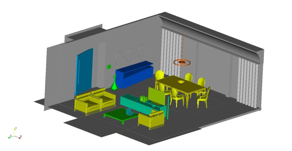
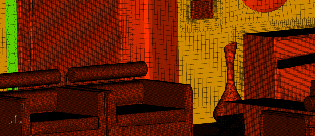
The facetSubset entities enable the user to control the refinement level at particular parts of the surface mesh. Here facetSubsets are applied on the parts that are coloured in Figure 3.
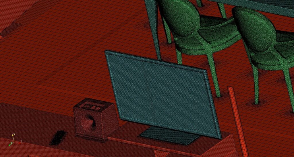
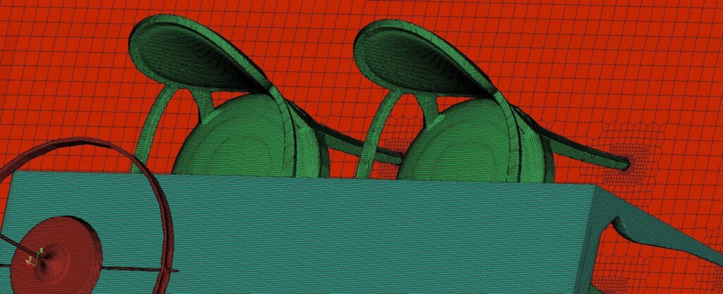
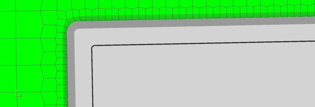
Figure 5 – 7 gives a detailed view of the surface of the generated volume mesh. Please note how very complex parts are nicely resolved with a high-quality mesh. Useful information regarding facetSubset entities can also be found in [2] while the ease of their creation on the complex geometries is shown in [3].
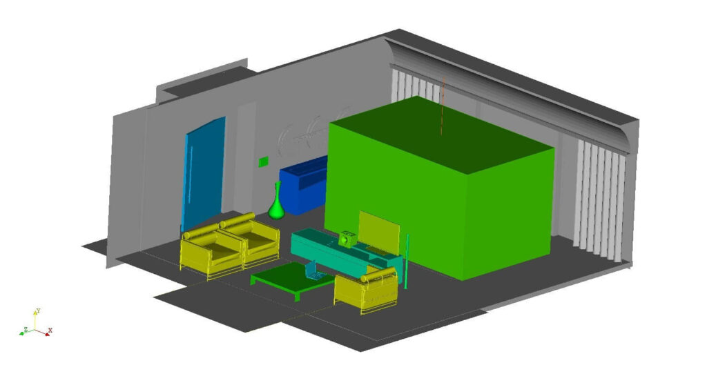
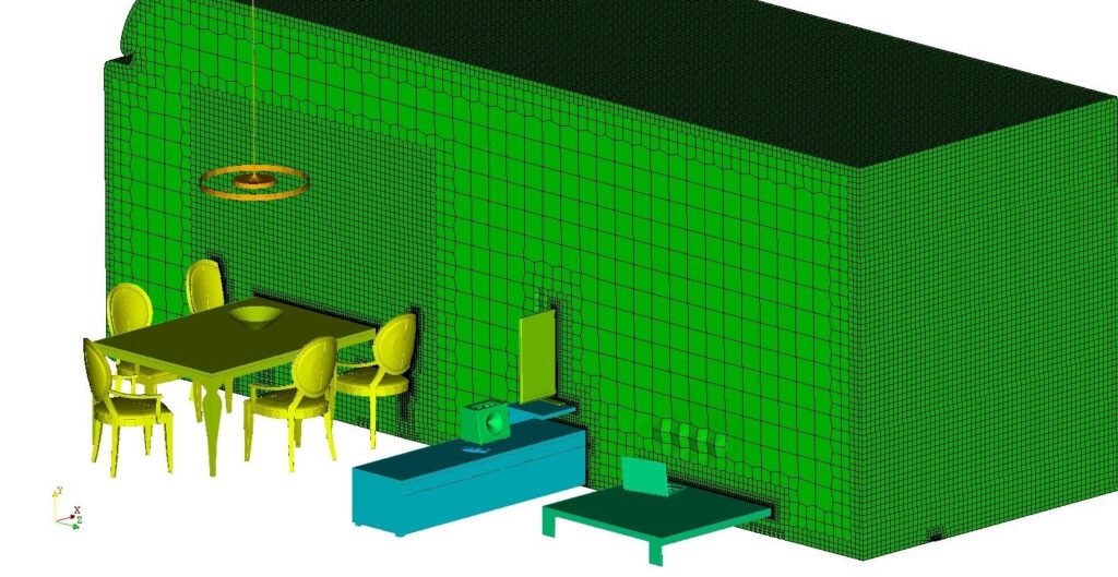
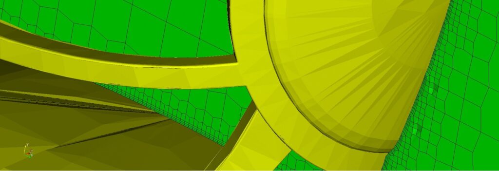
The mesh resolution in the zone of the special interest can be easily handled via the Object-based refinement option as shown in Figure 4. The procedure starts by defining a primitive object (e.g. box, sphere, or cylinder), and positioning it where needed followed by the specification of the desired mesh resolution inside this region. Please note that the zone embedded in a box from Figure 4 has increased mesh resolution (see Figure 8). More details about available refinement options one can be found in [2] and examples are provided in [4].
The boundary layers can be defined on every patch in the domain. When defined, they are extruded over the complete part they are applied to. This can be seen in Figures 9 and 10 where the boundary layer is extruded over the television and the chair respectively.
The complete mesh consists of 6828911 cells whereas 6231339 cells (91.25%) are hexahedral cells, which are proven to result in the highest solution accuracy [5]. In addition, there are 596824 (8.74 %) polyhedral cells that follow the hexahedral cells in solution accuracy [5]. Finally, there are 748 (0.01%) prisms.
Numerical Simulation
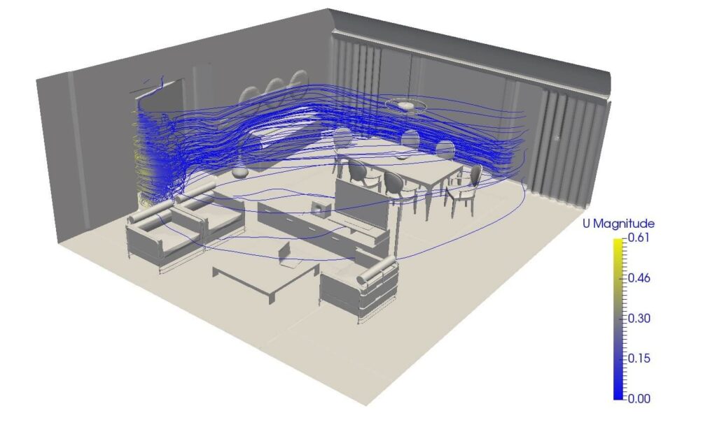
An unsteady, turbulent, incompressible, isothermal flow is computed on the generated mesh. The mathematical model consists of the continuity and momentum equations while the turbulence is modeled using the k-ω SST turbulence model with the standard coefficients. The volumetric flow rate of air through the inlet door is 500 m3/h. The rightmost window from Figure 3 is considered to be open and is defined as an outlet. The remainder of the domain are walls. The computation is carried out using OpenFOAM’s pimpleFoam solver. The computational results are shown in Figure 11.
Conclusion
This report presents an application of CF-MESH+ in CFD analysis of HVAC flows on a detailed geometry. It is also shown that the available mesh refinement options enable fast and simple mesh generation. Finally, the quality of the generated mesh is validated by the performed numerical simulation.
I hope that you have found this post useful and that it has made you curious to try out our latest CF-MESH+, designed to alleviate the pain of meshing. You can also subscribe to our newsletter to stay informed on our newest developments.
Acknowledgment
The authors thank Frederico Costa for providing us with the room geometry.
References
[1] Cukrov, A., Lugarić, T. and Juretić, F.: CF-MESH+ – An Automatic Finite Volume Mesh Generator, Proceedings of 7th Meeting of Croatian Society of Mechanics, Split, 2016. (in Croatian)
[2] Juretić, F.: cfMesh User Guide, Creative Fields, Zagreb, 2015.
[3] Cukrov, A. and Juretić, F.: Automatic Hex-Dominant Mesh Generation for CFD Analysis of Formula One Car with CF-MESH+, White paper, Creative Fields, Zagreb, 2016.
[4] Cukrov, A.: Quick Start With CF-MESH+, Creative Fields, Zagreb, 2016.
[5] Juretić, F.: Error Analysis in Finite Volume CFD, PhD Thesis, Imperial College London, United Kingdom, 2004.
- Is it Always the Mesh? Part 5: Boundary Layer Meshing
- 5 Most Important Steps in CF-MESH+
- Introducing Enhanced Anisotropic Meshing in CF-MESH+ 5.1.0
- Is it Always the Mesh? Part 4: Cell Types
- How To Get Support For CF-MESH+ License
By Alen Cukrov and dr.sc.Franjo Juretić
")
