Quite often, I hear complaints about non-orthogonality, the required number of non-orthogonality correctors to achieve convergence, and how it is worthless even trying to run a solver on a mesh, etc. The point of this series of posts is to give you an overview of the popular myths and to help you understand what is going on in your Finite-Volume CFD code and how to interpret mesh quality checks for your problem. The goal of this post is to demystify the impact of volume ratio on the accuracy and the stability of simulations solving the pressure equation.
Have you ever stumbled upon a problem that you cannot get a simulation to converge because the pressure constantly diverges? You have:
- Checked all boundary conditions, and they are all correct.
- Tried diffusive discretisation schemes to tame the solution.
- Noticed that none of the linear solvers can achieve convergence.
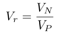
Well, these are all symptoms most often related to problems with a severe volume ratio somewhere in the mesh. The volume ratio is defined as the ratio between the volume of the cells sharing a common face:
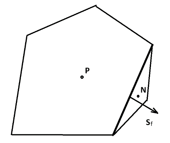
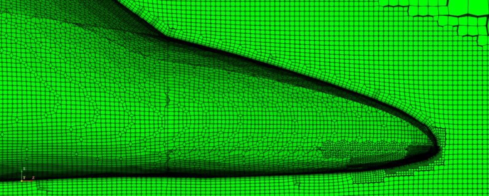
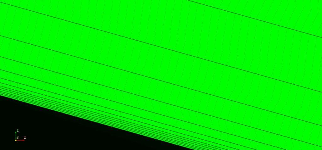
The picture below represents the situation at problematic locations in the mesh:
If you can find the time to visit my previous posts on skewness and non-orthogonality, it can be noticed that volume ratio does not play a role in convection, diffusion and source terms. In addition, all these terms can be stabilised by adding some numerical diffusion to problematic regions.
To understand how the volume ratio influences the pressure equation, let us start with a brief explanation of how the pressure equation is derived. The pressure equation is needed to calculate the pressure field and the fluxes conserving the mass. The pressure equation can be derived from a semi-discretised form of a momentum equation:
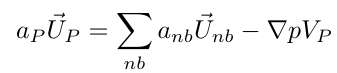
where the velocity from the equation above can be substituted into the continuity equation:
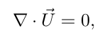
to result in the equation for pressure:
When the pressure equation is discretised using the Finite Volume Method, we achieve strong coupling of pressure between the neighbouring cells in the spirit of the Rhie-Chow interpolation. However, the coefficient in front of the pressure gradient is dependent on the cell volume, and this requires some further analysis to understand how it influences the solution procedure. When the pressure equation is discretised using the Finite Volume Method, the integration over volume can be represented as a summation over faces:

where the surface-normal gradient is not of prime importance and is left in the original form. From the equation above, cell volumes play an important role in the interpolated values at faces. When the volume ratio is inserted in the equation above:

it is possible to distinguish two critical scenarios:
- Volume ratio tends to zero – in this case, the neighbour part is small and it does not influence the coefficient at a face. Furthermore, the interpolation coefficient fx also tends to zero! This means that the neighbour no longer influences the value of the pressure in the current cell! These cells become decoupled, and this causes problems for the linear solver, causing strange pressure behaviour.
- Volume ratio tends to infinity – when the neighbour cell is much larger than the current cell results in a large interpolation coefficient at a face dominating over coefficients at other faces. This results in a cell being decoupled from other neighbours! This causes problems for the linear solver and often results in unphysical values of pressure in this cell.
Key takeaways for volume ratio
The most important takeaways about volume ratio are:
- Keep the transition of cell volume as uniform as possible.
- It causes problems with the solution of the pressure equation derived in the spirit of the Rhie-Chow procedure. It does not affect other equations in the system.
- Problems with volume ratio are best avoided by adopting some tips and tricks for mesh generation:
- Avoid extremely sharp feature edges – boundary layers cannot exist there. They must be collapsed, and this can lead to a problematic volume ratio.
- Avoid rapid transitions of cell size near the boundaries and feature edges.
- Use controls for controlling the volume ratio.
I hope that you have found this post useful, and that it has made you curious to try out our latest CF-MESH+, using the knowledge presented in this post, designed to alleviate you from the pain of meshing. Feel free to subscribe to our newsletter to follow the latest news in CFD meshing techniques.
- How to install a trial version of CF-MESH+
- Our best meshing practices for high-quality CFD simulations
- Is it always the mesh? Part 7: Volume Ratio – the Secret Killer Nobody Talks About
- Automatic Acute Edge Detection and Fillet Creation Algorithm
- Join us at the upcoming webinar “Next-Gen Meshing Technology at IANUS” with CF-MESH+
")
