Introduction
The main goal of this post is to give you the best meshing practices for high-quality CFD simulations, regarding geometry preparation, cell sizing techniques and boundary layer generation.
You’ve probably heard the phrase: “Garbage in – garbage out.”
This is often true in CFD, as garbage mesh results in garbage simulation. Poor mesh quality can lead to:
- Poor convergence
- Low simulation reliability
- Wasted engineering time
While some issues can be masked or tweaked using discretisation schemes, you can’t fix a fundamentally bad mesh with solver settings.
A good meshing strategy saves time, improves simulation reliability, and maximises the value of your computational resources.
Geometry preparation
Meshing always starts with the geometry, and CFD engineers often have to work with geometries that were not created by professionals in the field.
This often results in imperfect, overly complex, or unclean geometries, which can complicate the simulation process.
To ensure a smooth meshing workflow, follow these key preparation steps:
1) Remove non-essential details

Eliminate small features and parts that don’t influence the simulation outcome. Because these can unnecessarily increase the mesh size and time needed to get a good mesh.
2) Resolve intersections and overlaps

While a lot of meshers, including our in-house developed solution CF-MESH+, can tolerate and generate meshes on such geometries, clean and well-defined surfaces give the mesher better information, leading to more robust and reliable meshes.
For example, avoiding overlapping patches helps the multidomain mesher clearly define interfaces and preserve surface/patch integrity.
3) Fix acute edges
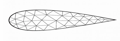
Sharp features such as trailing edges tend to reduce the local feature size to near-zero, making them difficult to mesh. These do not exist in physical models, and it’s much better to apply a fillet to define a finite feature size, allowing accurate resolution with at least two cells across the fillet.
To automate cleanup, we developed the ‘Surface Cleaner’ feature. It resolves intersections and overlaps using a user-defined tolerance. This reduces manual work and ensures the mesher works with a well-defined surface, improving both the quality and reliability of the mesh.

We also developed a ‘Fillet Tool’ to automatically detect acute edges and apply fillets based on user-defined tolerances.
A good rule of thumb:
If angle < 150° → keep the feature edge
If angle > 150° → apply a fillet
This dramatically improves mesh quality in critical regions by reducing skewness and better aligning cells with the geometry.

Supported geometry formats in CF-MESH+:
- .stl
- .step
- .igs
- .brep
We strongly recommend using .step files whenever possible, as they are the best for preserving geometries’ integrity.
Cell sizing techniques
CF-MESH+ offers flexible refinement options:
- Manual refinement – based on patches or geometric subsets (edges, faces, points)
- Automatic refinement – driven by curvature analysis, ray casting, feature size detection…
To accurately capture details and generate high-quality boundary layers, at least two cells across the smallest features are desired. In most cases, a feature refers to, for example, the radius of a curved surface or the gap between two closely spaced surfaces.


For a sculpture of Edgar Allan Poe, using automatic curvature refinement alone, we achieved a high-resolution mesh that accurately captures complex surface details, with minimal manual effort and without unnecessary refinement in areas where it is not needed. In this context, the curvature radius defines the feature size, and the mesher automatically ensures at least two cells across each curvature radius.
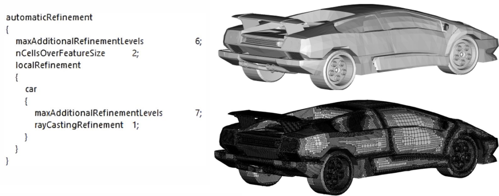
In another example, we used ray casting refinement for a car model. This geometry contains mostly sharp edges, and the required refinements are primarily due to thin gaps between flaps and other parts. The ray casting method works by casting rays away from the surface and refining the mesh wherever a gap—representing the feature size—cannot accommodate at least two cells by default. The user can also adjust the level of refinement by increasing or decreasing the number of cells across the feature size, allowing for more control over mesh resolution.

Boundary layer generation
CF-MESH+ provides detailed control over boundary layer generation, which is essential for accurately capturing near-wall physics. Once the feature size is well-defined and properly resolved, generating a high-quality boundary layer becomes straightforward.
In the example below, we used the “3) Thickness ratio | 1st layer thickness” option. This approach allows precise control over the inner portion of the boundary layer using a specified thickness ratio. In our case, we defined a total of 20 boundary layer cells—dividing them into 15 outer layers and 5 inner layers.
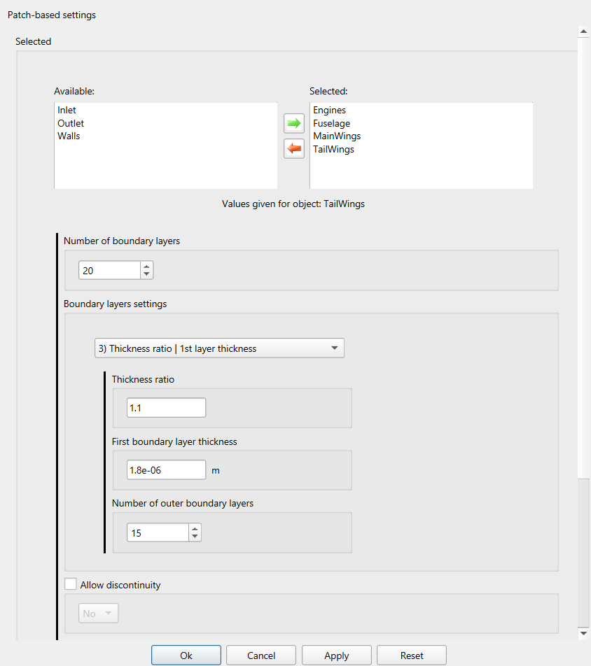
The outer section of the boundary layer is automatically managed by the meshing algorithm, which optimises the outer thickness ratio to ensure a smooth transition from the inner boundary layer to the core mesh.
To achieve a target y⁺ value, it is important to calculate the appropriate first-layer thickness. If you’re unsure how to perform this calculation, we recommend using an online wall distance or y⁺ estimation tool.
While CF-MESH+ allows the generation of very thin layers, as demonstrated in this example, be aware that you can also create layers that are too thin. Extremely high aspect ratios can lead to floating-point precision issues in some solvers. If such problems occur, a recommended solution is to refine the mesh by a few levels in all directions near the boundary region. This helps improve aspect ratios and enhances solver stability.
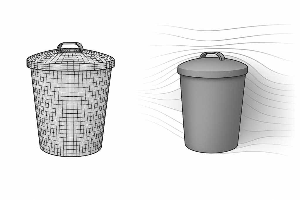
In the next example, we compare the boundary layers of two meshes—one with a fillet applied and one without. You may recall this geometry from an earlier section where we discussed the fillet tool. This comparison highlights how critical proper feature resolution is to mesh quality.
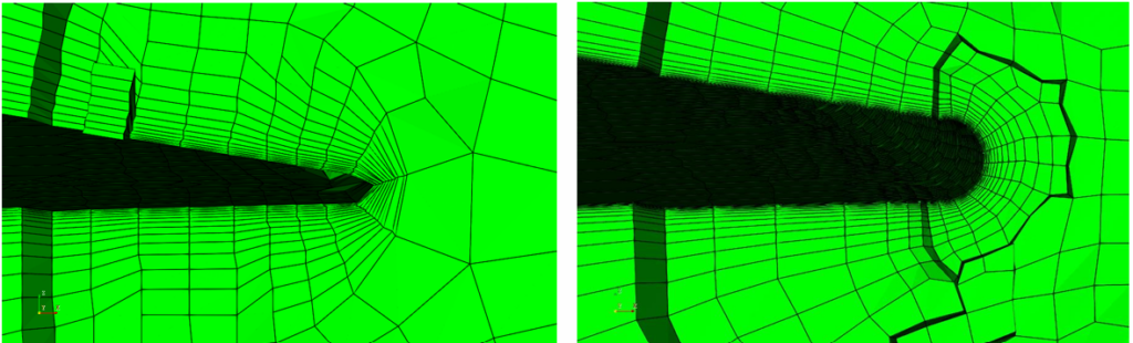
By applying a fillet and ensuring the feature size is captured using at least two cells, the surface integrity is significantly improved. As a result, the boundary layers generated are much cleaner and more consistent.
Both versions of the model were meshed using identical settings, allowing for a direct comparison of mesh quality metrics. Notably, the majority of poor-quality cells in the unfilleted version are clustered near sharp edges. This reinforces the importance of geometric smoothing and appropriate resolution when preparing complex models for meshing. As noted earlier, sharp edges, which do not exist in the real world, are often modelling artefacts intended to simplify geometry or reduce the time needed for modelling. At these edges, the feature size tends toward zero, making it impossible to capture perfectly.

Conclusion
In conclusion, always take the time to prepare your geometry properly, whether you’re working in CAD or using our or some other pre-processing tools. Proper geometry cleanup and simplification can save significant time, reduce computational cost, and prevent common meshing issues down the line.
And yes, it’s worth repeating: feature size matters. To accurately capture surface details and generate clean, high-quality boundary layers, ensure there are at least two cells across the smallest features.
By following these straightforward guidelines, you’ll consistently produce robust, high-quality meshes that support stable and accurate simulations, right from the start.
I hope you have found this post useful and that it has sparked your interest in trying out CF-MESH+ and its automatic fillet creation feature. You can also subscribe to our newsletter to stay informed on our newest developments.
- How to install a trial version of CF-MESH+
- Our best meshing practices for high-quality CFD simulations
- Is it always the mesh? Part 7: Volume Ratio – the Secret Killer Nobody Talks About
- Automatic Acute Edge Detection and Fillet Creation Algorithm
- Join us at the upcoming webinar “Next-Gen Meshing Technology at IANUS” with CF-MESH+
")
