Introduction
In Computational Fluid Dynamics (CFD), maintaining mesh quality is crucial for achieving convergence and accuracy. A common issue arises when dealing with acute feature edges—regions where two parts of the surface meet at sharp angles. These edges introduce significant challenges in volume mesh generation. Sharp edges, which do not exist in the real world, are often modelling artefacts intended to simplify geometry or reduce the time needed for modelling. However, acute feature edges are extremely challenging for the meshing process because they can result in regions of excessively small feature size as well as increased skewness, poor gradient accuracy, and difficulties in achieving convergence during simulations. You can read more in our blog post about Feature edges and corners.
To address this issue and enhance the overall meshing process, for CF-MESH+ v.5.4.0, we have developed an algorithm that automatically detects acute edges in a geometry and applies a fillet with a specified radius to smooth these transitions.
Fillet acute edges tool
The newly developed Fillet Acute Edges Tool, now available in the Tools ribbon under Surface Tools, simplifies the process of handling acute edges in CFD meshing workflows. This user-friendly tool requires just two straightforward inputs:

1) Fillet radius
Specify the desired fillet radius to be applied at the detected acute edges. Similar to standard CAD tools, this parameter determines the smoothing radius for the fillet. If the local surface topology supports the given radius, but the surrounding surface geometry is non-flat, the tool automatically adjusts to create the maximum allowable fillet radius without compromising the surface topology. This ensures seamless integration of fillets into complex geometries.
2) Acute Edge Angle Tolerance
Set the angle tolerance to identify edges that require filleting. The tool detects edges where the intersection angle falls below the specified threshold and applies fillets accordingly. A good rule of thumb that serves quite well here is: If the angle is smaller than 150 degrees, it is fine to keep the feature edge. Otherwise, it is much better to create a fillet there. The angle tolerance can be set within a customizable range of 120–179 degrees, offering flexibility to suit various geometries and meshing needs.
3) Fillet Surface Deviation Tolerance
Fillet surface deviation tolerance is set to 10 degrees by default and can be adjusted within the range of 1 to 45 degrees. This parameter defines the maximum allowable angular deviation of the filleted part of the surface from the surface’s direction at the edge where the fillet is applied. It ensures that fillets are applied smoothly by preventing excessive distortion in the surface geometry or mesh, which can occur on highly curved or irregular surfaces. If the tolerance is exceeded, or the surface distance from the initial fillet direction exceeds the given fillet radius, then the maximum allowable radius is applied to those acute edges.
4) Fillet Only Specified Part
The fillet only specified part option allows you to apply a fillet with a specified radius only to a selected patch or subset of your geometry. It gives you precise control over where filleting occurs, which is perfect for refining critical regions without affecting the entire model.
This tool is designed to enhance mesh quality by smoothing problematic acute edges. In the following examples, we will demonstrate how the ‘Fillet acute edges’ tool updates geometries by automatically detecting and smoothing acute edges.
The first example showcases the geometry of a bridge, highlighting areas where acute edges are present in the surface mesh, particularly at the intersections where supporting pillars meet. The locations detected by the Fillet Acute Edges Tool are marked with blue dots for clarity.

In the next image, you can observe a close-up comparison, highlighting how the Fillet Acute Edges Tool transformed the bridge geometry.

Once the fillet is formed, you simply need to apply refinement to the resulting filletSubset or enable automatic curvature refinement. This ensures that the fillet is accurately captured in the volume mesh, maintaining high-quality mesh resolution and fidelity to the geometry.
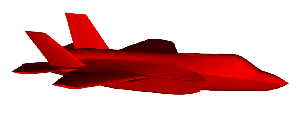
The next example highlights a geometry where this issue frequently arises—in the aeronautical industry. Specifically, we showcase an example of an F-35 aircraft.
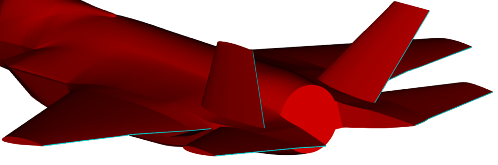
In the next image, the filletSubset is highlighted in blue, showcasing where the fillet has been automatically applied to the sharp edges at the ends of the wingtips.
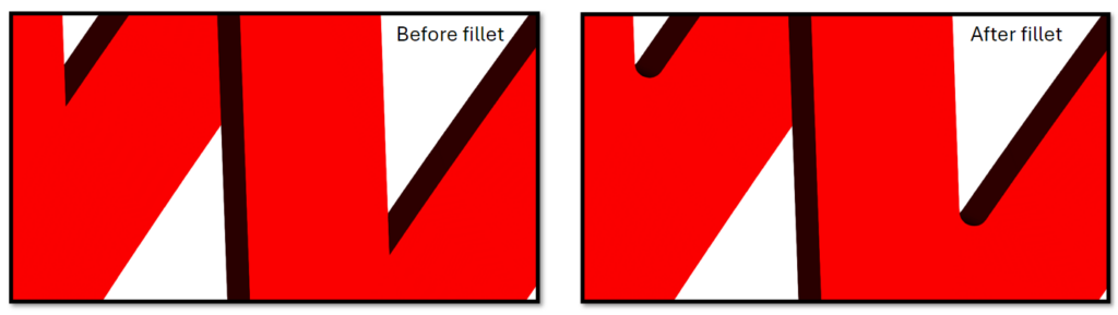
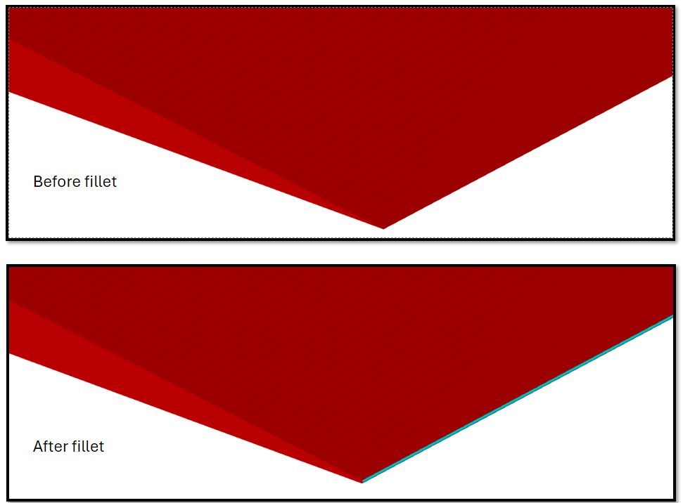
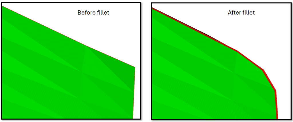
Here is a close-up of the end of an aircraft’s wing, showing the geometry before and after the fillet tool is applied.

Volume mesh comparison
In this segment of the blog post, we will compare the volume mesh generated on the geometry of a small aircraft, both with and without the application of the Fillet Acute Edges Tool. The goal is to highlight the difference in mesh quality and the impact of filleting acute edges on the overall mesh quality.
The next image shows the geometry we will use for the volume mesh comparison. The red parts of the geometry highlight the filletSubset, which is created after applying the fillet tool with a 130° angle tolerance.
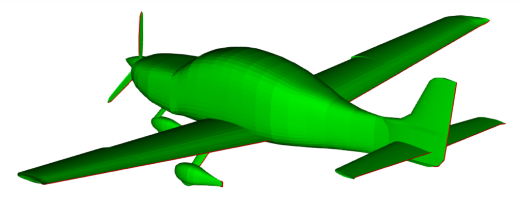
Here, we have applied a very small fillet radius to preserve the original geometry as much as possible, especially considering that many parts of the geometry have highly acute edges. In areas where the fillet is applied, the geometry may appear “tucked in” or slightly altered. To minimise this effect, we used a fillet radius of 0.0075 m. This small radius allowed us to maintain the overall shape of the geometry, ensuring that the modifications from the fillet tool do not cause significant distortion, keeping the geometry “tucked in” by no more than a few millimetres in the areas where the fillet is created. The next few images will showcase close-up views of the geometry, comparing it before and after the fillet is applied.

After applying the fillet and using cell sizes that match the characteristic feature dimensions, the resulting volume mesh shows a marked improvement in quality. The fillet helps eliminate sharp edges and abrupt geometric transitions, which reduces cell skewness and improves overall mesh smoothness. This results in a more balanced mesh with fewer distorted elements, leading to better numerical accuracy and more stable simulation performance.
The resulting mesh includes 15 boundary layers on the aircraft patch, with the first layer thickness set to 1e-5. Both meshes have approximately the same total number of cells and use the same cell size at the acute edges of the aircraft.
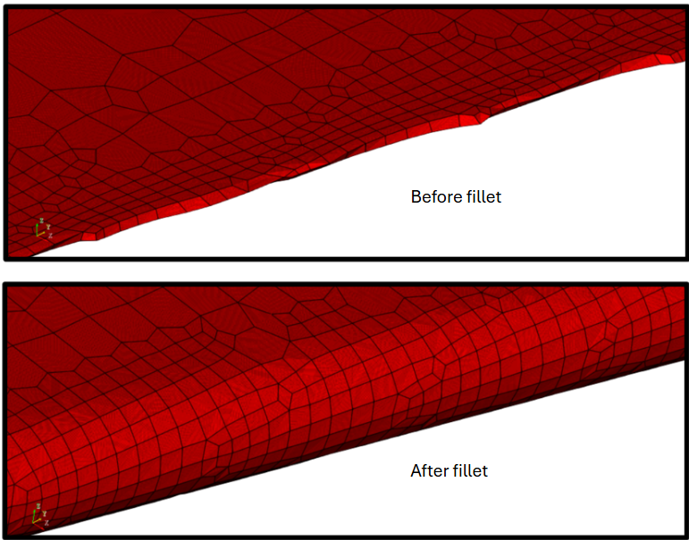
As shown in the images above, very acute edges in the geometry cause the local feature size to approach zero. In such cases, the volume mesh cannot accurately represent these regions, regardless of how small the cell size is. However, by applying a fillet to these sharp edges, the feature size becomes finite, equal to the fillet radius, and it can be effectively captured using just two cells across it. This leads to a much more accurate representation of the geometry. Mesh quality metrics, such as skewness, often improve significantly in these areas once the feature size can be properly resolved.
I hope that you have found this post useful and that it has made you curious to try out CF-MESH+ and its automatic fillet creation feature. You can also subscribe to our newsletter to stay informed on our newest developments.
- How to install a trial version of CF-MESH+
- Our best meshing practices for high-quality CFD simulations
- Is it always the mesh? Part 7: Volume Ratio – the Secret Killer Nobody Talks About
- Automatic Acute Edge Detection and Fillet Creation Algorithm
- Join us at the upcoming webinar “Next-Gen Meshing Technology at IANUS” with CF-MESH+
")
