Introduction
While the majority of our users rely on OpenFOAM solvers in their CFD workflows, we understand the importance of flexibility and cross-platform compatibility. That’s why CF-MESH+ has long supported a range of mesh export formats, including Fluent, CGNS, and AVL FIRE.
With the latest update, we introduce native support for SU2 mesh export. Users can now generate meshes in CF-MESH+ and export them directly to the native .su2 format, making it easier to integrate our meshing tools into SU2-based workflows.
In this post, we demonstrate the export process using two examples: a 2D NACA airfoil and a 3D jet aircraft geometry. Both examples highlight how CF-MESH+ handles different mesh structures and prepares them for SU2 compatibility.
NACA 2D wing simulation using SU2
CF-MESH+ creates 2D meshes by generating a single cell in the z-direction, forming a thin 3D layer. It uses two empty boundary patches, bottomEmptyPatch and topEmptyPatch, to define the top and bottom of this layer, while keeping the mesh effectively 2D for OpenFOAM solvers.
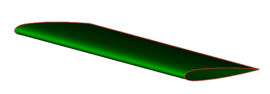
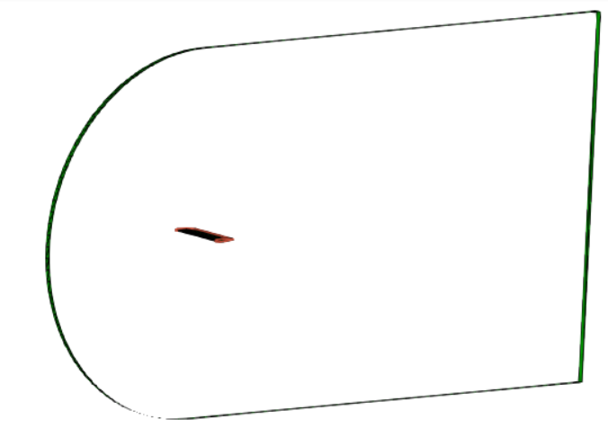
When exporting to SU2, CF-MESH+ takes advantage of this structure by using bottomEmptyPatch as the reference surface to generate a true 2D mesh in the .su2 format. Since SU2 uses planar 2D meshes rather than extruded volumes, the exporter converts the single-layer mesh into the appropriate 2D representation.
To create a 2D Cartesian mesh in CF-MESH+, the input surface file should consist of two open (non-closed) patches, as illustrated in the images below.
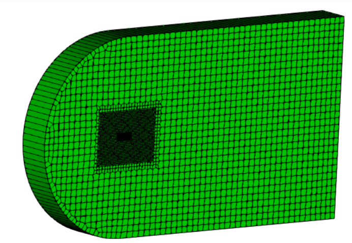
The resulting mesh is generated with a single cell in the z-direction, effectively producing a 2D mesh enclosed between bottomEmptyPatch and topEmptyPatch.
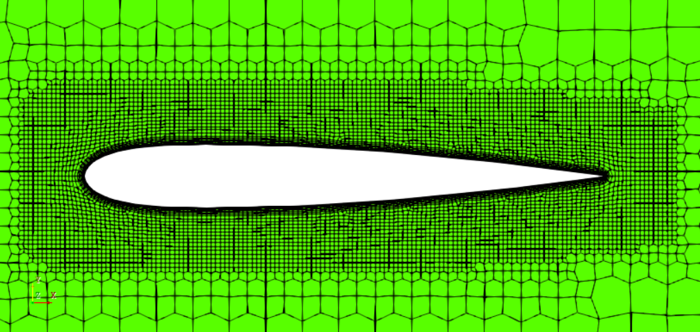
As noted earlier, only bottomEmptyPatch is used to define the planar mesh during export. Since the Cartesian meshing template in CF-MESH+ can produce both hexahedral and polyhedral cells, additional conversion is required to ensure compatibility with SU2, which does not support general polyhedral elements.
The exporter handles the conversion of unsupported polyhedral elements into supported element types and applies mesh smoothing as part of the export process. The resulting 2D mesh consists of SU2-compatible elements, such as triangles and quadrilaterals, while retaining the refinement around the airfoil geometry.
The following images show the exported mesh, including a closer view of the elements around the airfoil.
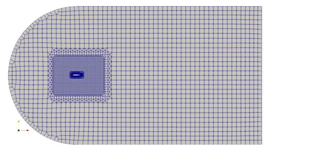
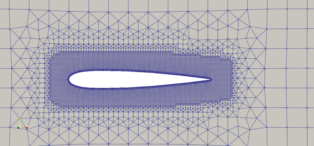
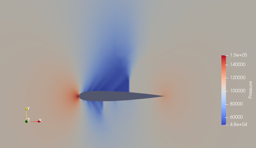
This mesh can then be used directly in SU2 simulations. In this example, we use a NACA airfoil geometry to solve the Euler equations. The freestream conditions are:
-Pressure: 101,325 Pa
-Temperature: 273.15 K
-Mach number: 0.8
The objective is to compute both the flow field and the adjoint solution, focusing on minimizing drag on the airfoil. The following image shows the flow.vtu results file visualized in ParaView.
Jet 3D meshing for SU2
For the 3D example, we use a jet aircraft geometry to demonstrate the export of a predominantly hexahedral mesh.
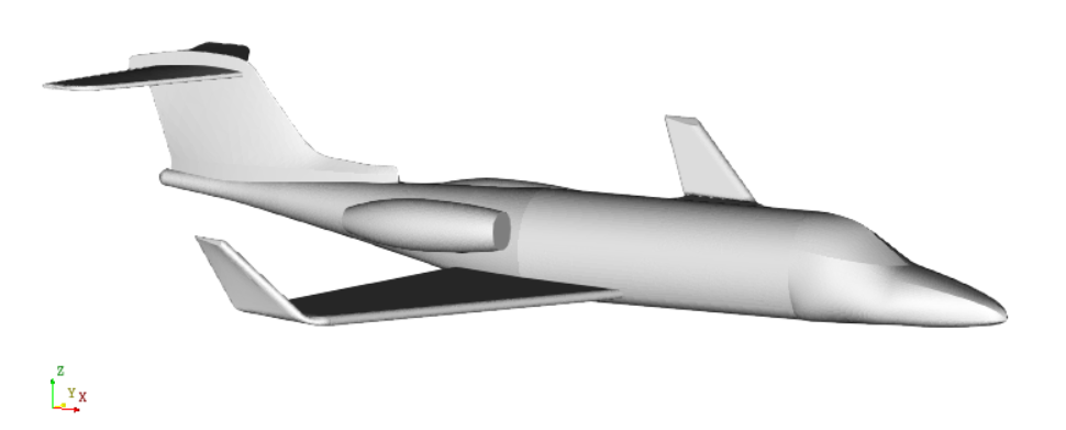
The mesh was generated using the CF-MESH+ hexMesh template, which creates a mesh composed primarily of hexahedral elements, with a small number of other standard element types where required by the geometry and mesh topology.
Unlike the 2D Cartesian mesh example, this mesh does not contain any general polyhedral cells. Therefore, no polyhedral cell decomposition is necessary before exporting it to SU2.
The generated mesh contains approximately 2.4 million cells, with more than 99.98% of them being hexahedra. The remaining cells are prisms, pyramids, and tetrahedra, all of which are supported by SU2.
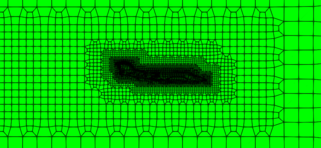
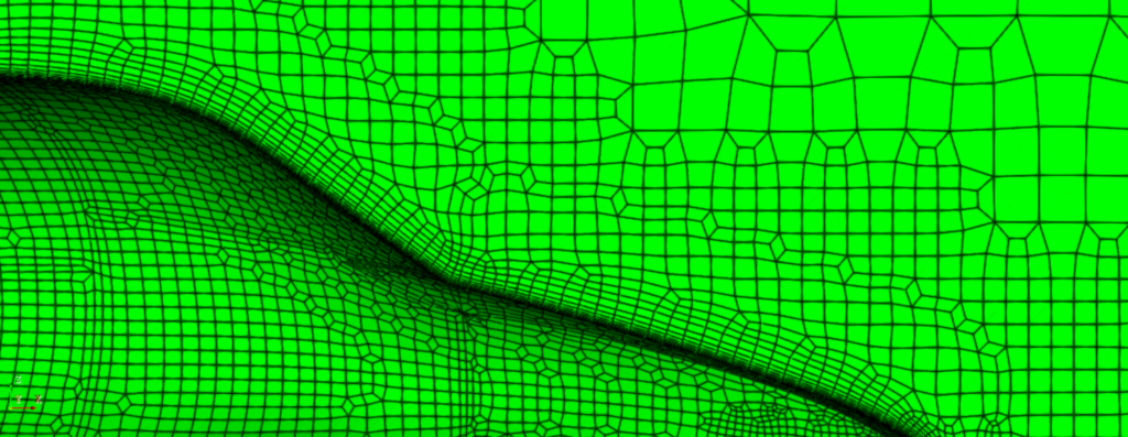
Unlike the 2D Cartesian mesh example, this mesh does not contain any general polyhedral cells. Therefore, no polyhedral cell decomposition is necessary during exporting it to SU2.
Once the mesh has been generated, it can be converted directly into the .su2 format using the new exporter. The conversion preserves the mesh geometry, element connectivity, and boundary patch definitions, producing a mesh in SU2’s native format.
For this example, the original mesh contains three boundary patches: Jet, Farfield, and Symmetry. These are retained as boundary markers in the exported SU2 mesh, allowing the corresponding boundaries to be identified in subsequent workflows.
This demonstrates how CF-MESH+ can generate and export large 3D meshes while maintaining compatibility with SU2’s supported element types.
Alternatively, if the cartesianMesh template is used for this workflow, the generated mesh will contain polyhedral cells. Since SU2 does not support general polyhedral elements, the exporter automatically decomposes them into supported element types, following the same approach described in the 2D NACA airfoil example. This ensures that meshes generated using either meshing template can be exported to SU2 format.
Conclusion
CF-MESH+ provides automated mesh generation tools for a wide range of 2D and 3D geometries, with multiple meshing templates and export formats to accommodate different CFD workflows.
With the introduction of native SU2 export, users can now prepare meshes for SU2 directly from CF-MESH+, without relying on external mesh conversion tools.
As demonstrated by the NACA airfoil and jet aircraft examples, the exporter supports both 2D and 3D meshes, handles the necessary element conversions, and preserves boundary information in the resulting .su2 files.
CF-MESH+ bridges the gap between efficient meshing and solver flexibility, making it a valuable part of any CFD workflow.
I hope you have found this post useful and that it has encouraged you to try out CF-MESH+ and explore its automated meshing capabilities and new SU2 export functionality. You can also subscribe to our newsletter to stay informed about our latest developments.
You may also be interested in: