CF-MESH+
Automatic meshing workflow software with an intuitive user interface. Free trialBook a consultationCF-MESH+ benefits
Boundary layers
Additional development of our CF-MESH+ software, tailor-made for your needs.
Multi-domain meshing
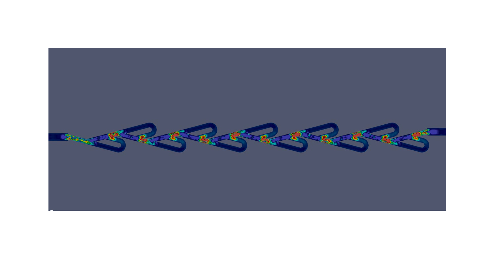
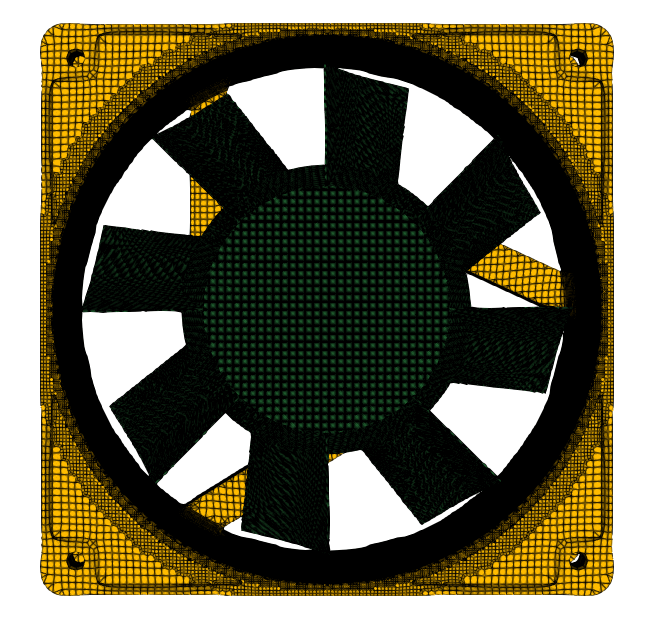
Enables generation of conformal interfaces between the multiple domains
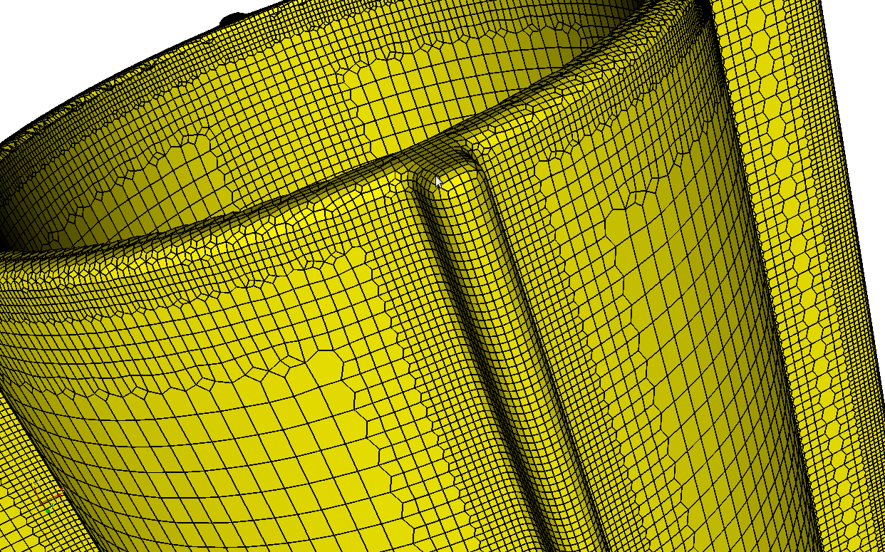
Automatic meshing workflows
Producing meshes in a single run with simple prior setup.
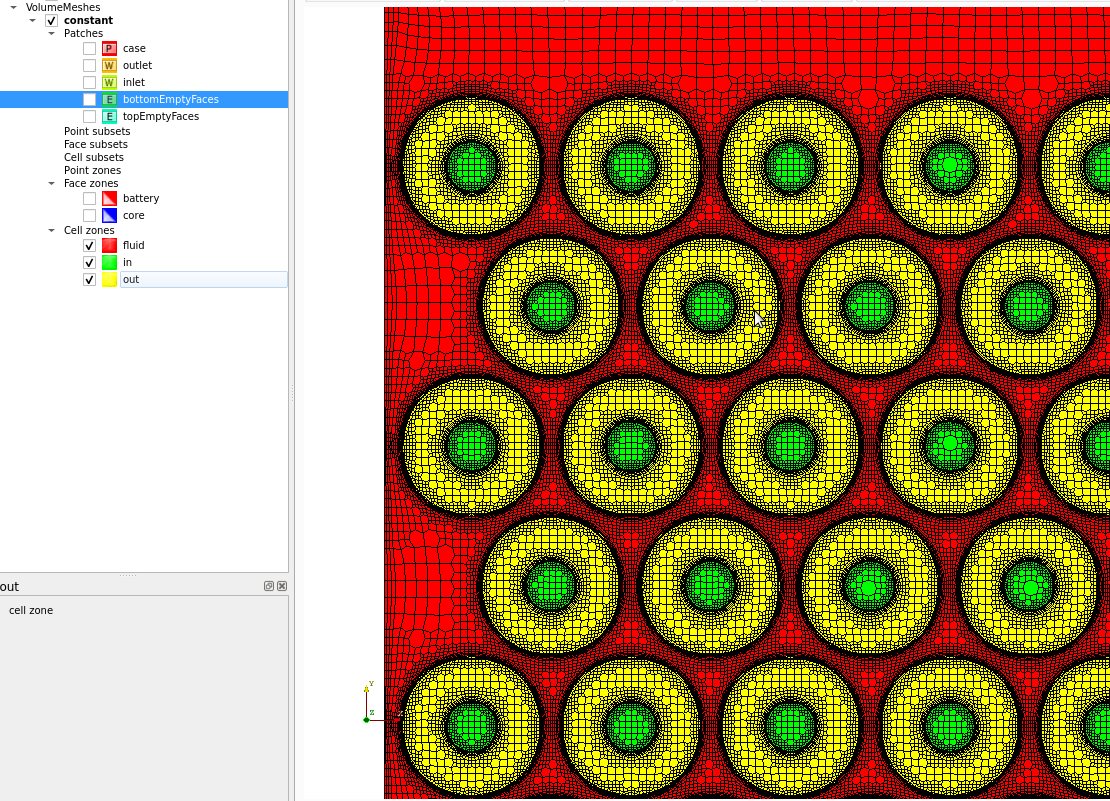
Mesh refinement
Driven by the user settings. Automatic refinement criteria also available
ABOUT THE SOFTWARE
Engineering simulation challenge
Engineering simulation methods have gained popularity due to large increase in computer power and development of feasible numerical methods. However, these methods require spatial discretization often represented in a form of a mesh or a point cloud.
A typical CFD (Computational Fluid Dynamics) simulation consists of five steps: geometry preparation, volume mesh generation, simulation setup, a solver run and post-processing. The first two steps are most labor consuming. Most often geometry is exported from a CAD package, and this process quite often results in problems, which are difficult for repairing.
Volume mesh generation has been a research topic over many decades. Block-structured meshes allow for low memory usage due to the order of cells in the mesh. However, they are difficult to generate in complex geometries without sacrificing geometry details. This has motivated development of unstructured methods which are more automatic, but still require high quality input data. Recently, a novel class of methods, so called inside-out, became popular due to high level of automation, speed and simplicity.
Who is it for?
CF-MESH+ is designed for engineers and other experts using CFD in their product development and research. It is a perfect companion to those who require an efficient, easy-to-use, yet fully automated meshing process able to resolve complex domains faced in industrial settings.
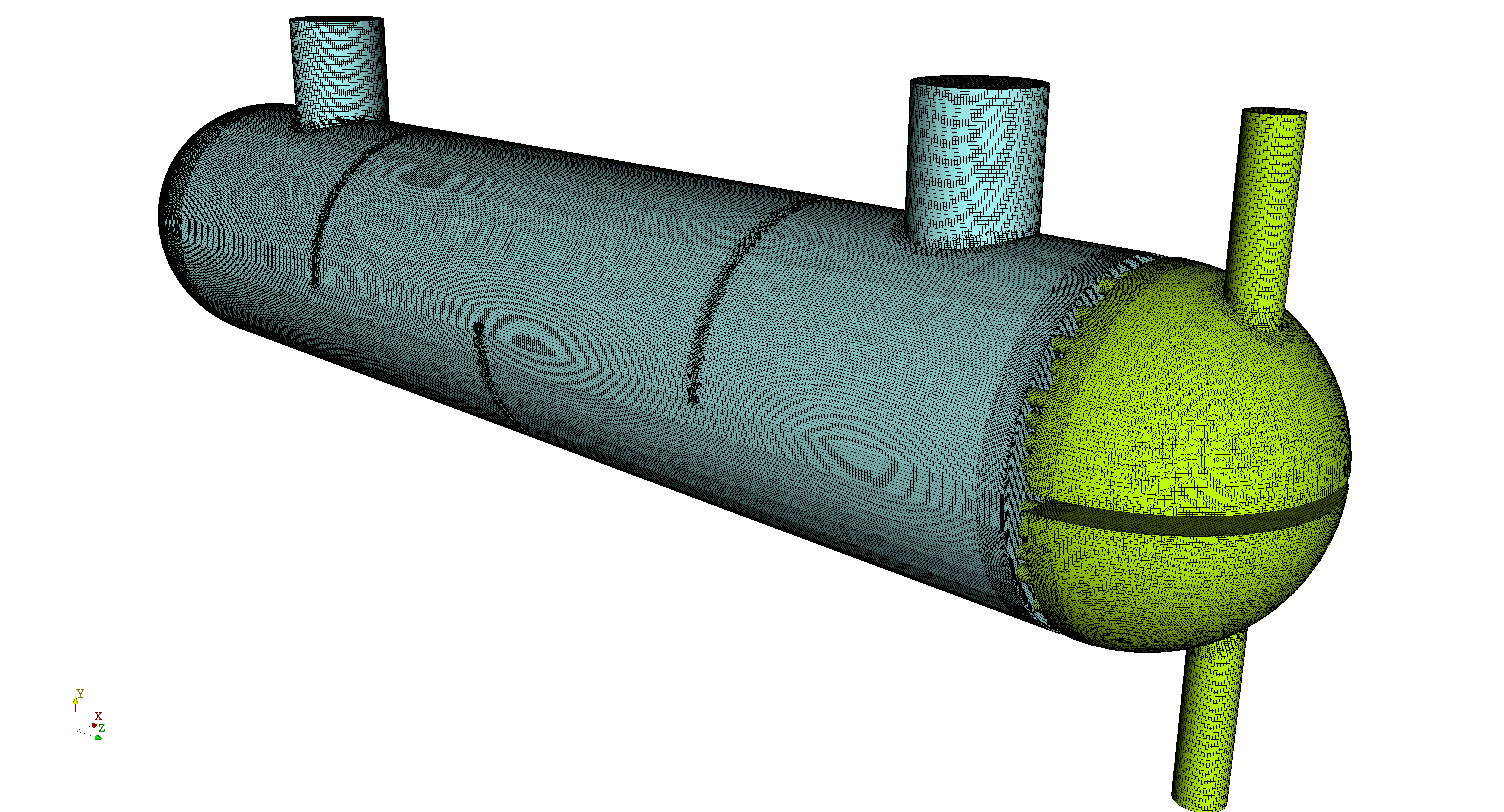
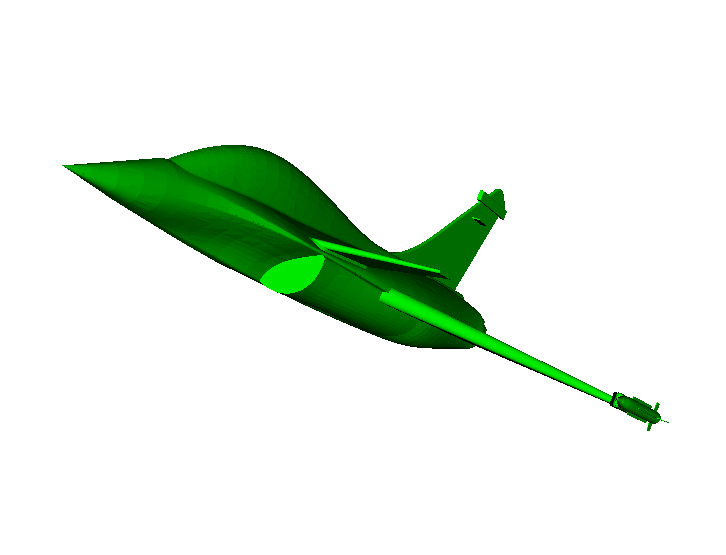
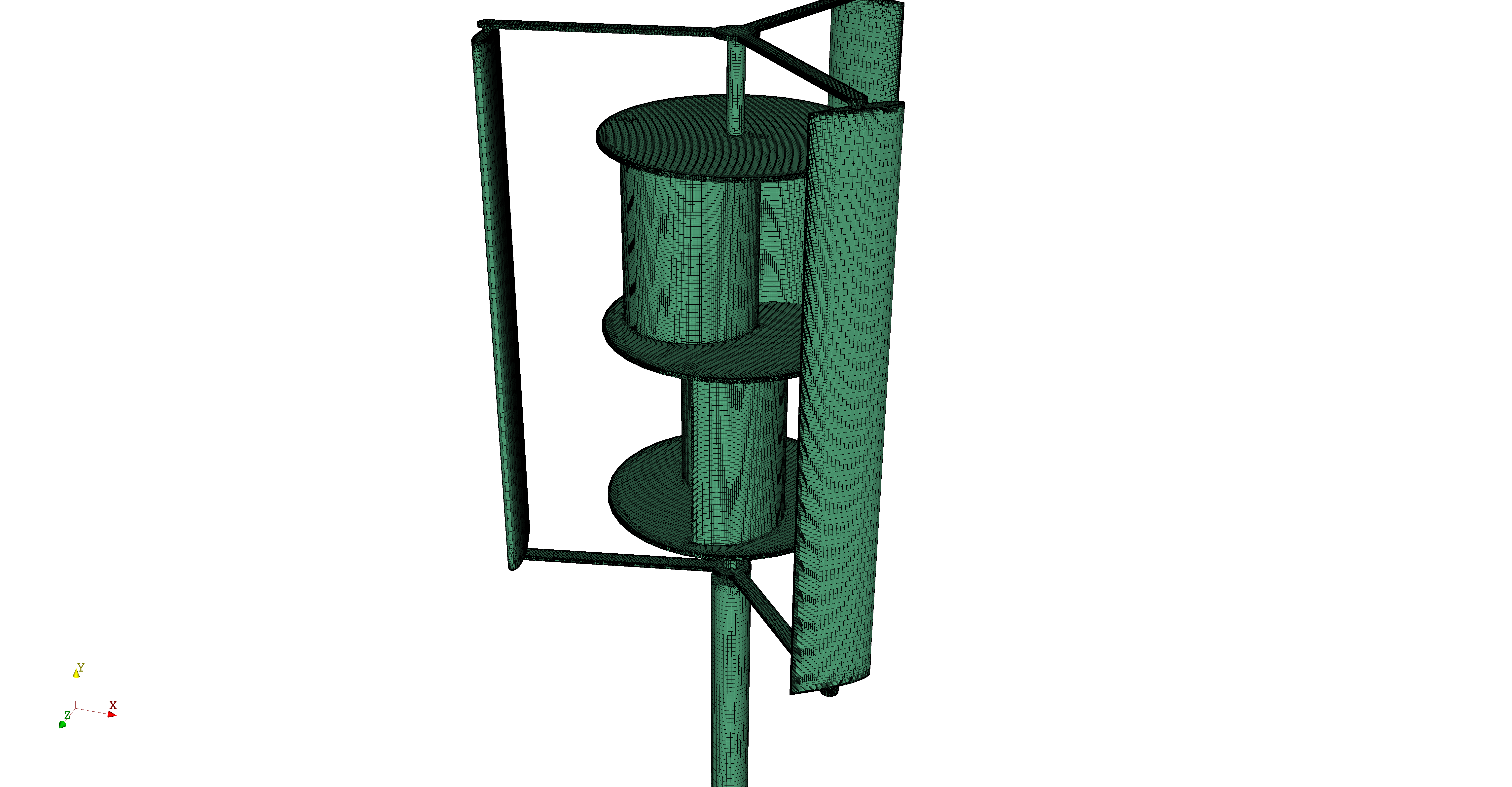
The volume meshes generated by CF-MESH+ are delivered in OpenFOAM, ANSYS Fluent or neutral (CGNS) formats, and are highly suitable for use by a multitude of popular CFD software. The meshes have been successfully used in various types of CFD simulations, from the automotive aerodynamics (see e.g. our F1 car case study or Ahmed body meshing example video), hydrodynamics, human hemodynamics (blood vessels), HVAC, to chemical processing, or civil engineering. Due to its ability to generate volume meshes composed of tetrahedral elements only, the software has also found successful usage within the finite element analysis (FEA) realm.
Benefits for you
Resolving complexity. The implemented meshing methodology is designed to provide quality meshes on arbitrarily complex geometries. The available workflows are robust and sensitivity to input data is minimized.
Simple setup. Minimum user input is needed to prescribe settings for the meshing process.
Speed. The meshing workflow is fully automated and meshes are obtained in a single run. Implemented algorithms are parallelized and computational resources are used efficiently. Meshing processes can also be set up and started from the batch mode (scripting).
Access to expert support. Our mission is to help our customers being productive in their simulation efforts. While the software is being regularly upgraded with the new features that facilitate this process, our customers also greatly benefit from our meshing expertise and support. In certain circumstances, it is also possible to provide for customized meshing solutions and workflows.
How the software works
Mesh templates: The implemented mesh templates are Cartesian (2D and 3D), hexahedral, tetrahedral, and polyhedral.
Input geometry: Geometry is given as a surface triangulation. Patches are defined on the input geometry and transferred onto the volume mesh. Subsets (points, facets) are used for mesh generation, but are not transferred onto the volume mesh. Feature edges are defined by the user before volume meshing.
Refinement settings: Refinement zones can be specified globally or locally. One can specify the maximum cell size, the number of refinement levels or the boundary cell size, and the refinement thickness. For local refinement one can u se patches, subset, edges and/or points. In addition, refinement zones can be specified by using primitive objects and/or auxiliary surface meshes. Finally, the automatic mesh refinement based on estimated feature size, curvature or other parameters is also available.
Boundary layers: Boundary layers can be prescribed globally or locally by specifying the number of layers, the thickness ratio, the thickness of the first layer, or the total layer thickness.
Gaps and thin features: Global and local options are available to preserve or remove cells in thin gaps.
Parallelization: Multi-threading in mesh library is implemented by using OpenMP, which is supported by most modern C++ compilers.
Graphical user interface: Software is built around a modern ribbon-based front-end with minimalistic set of buttons. Easy usage is further enhanced via built-in help system, intuitive workflow and input validation.
Key meshing features
1. BOUNDARY LAYERS
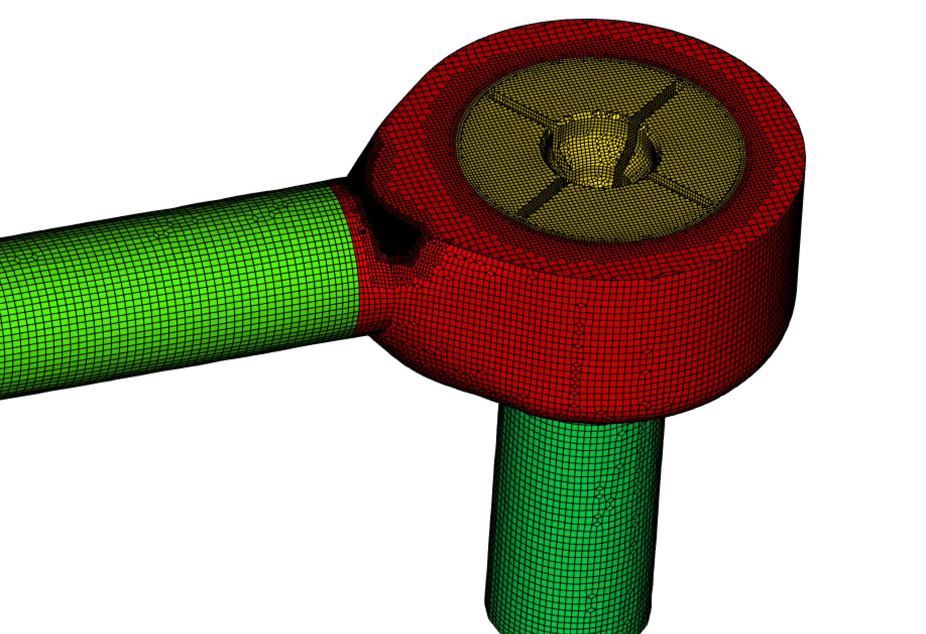
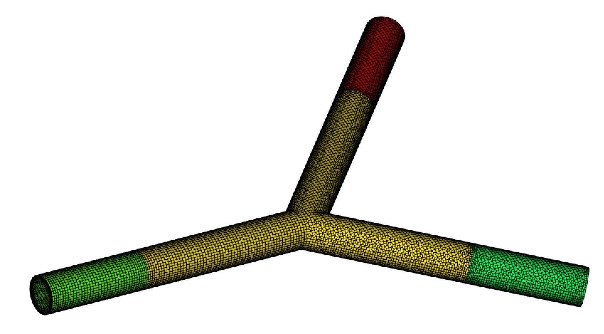
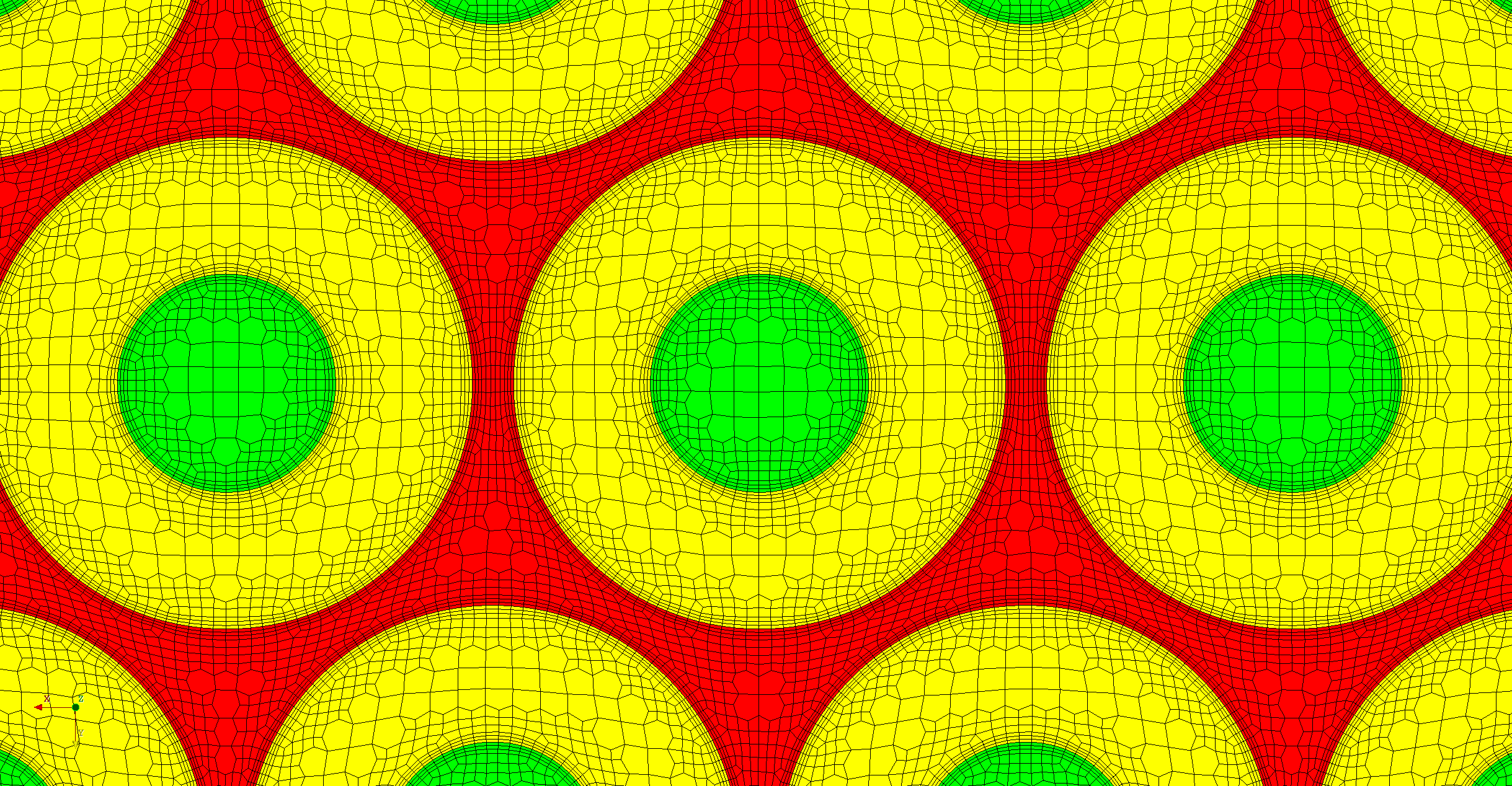
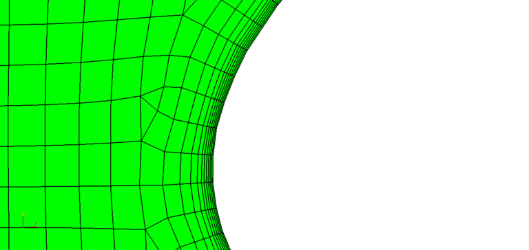
CF-MESH+ features superior boundary layer generation capabilities. Smooth boundary layers are generated in automatic fashion. One can prescribe the boundary layers at general boundaries or at selected patches only. The user is able to control the total thickness of the boundary layers, which enables for smooth transition towards the inner domain cells. Depending on the flow conditions, y+ value can also be controlled via explicitly prescribing the thickness for the first boundary layer.
Additionally, one is able to activate/deactivate the boundary layer topology at special boundary types, e.g. inlet/outlet patches or symmetry planes. Boundary layer optimisation parameters can be prescribed.
2. MULTI-DOMAIN MESHING
Download multi-domain/baffles meshing examples:
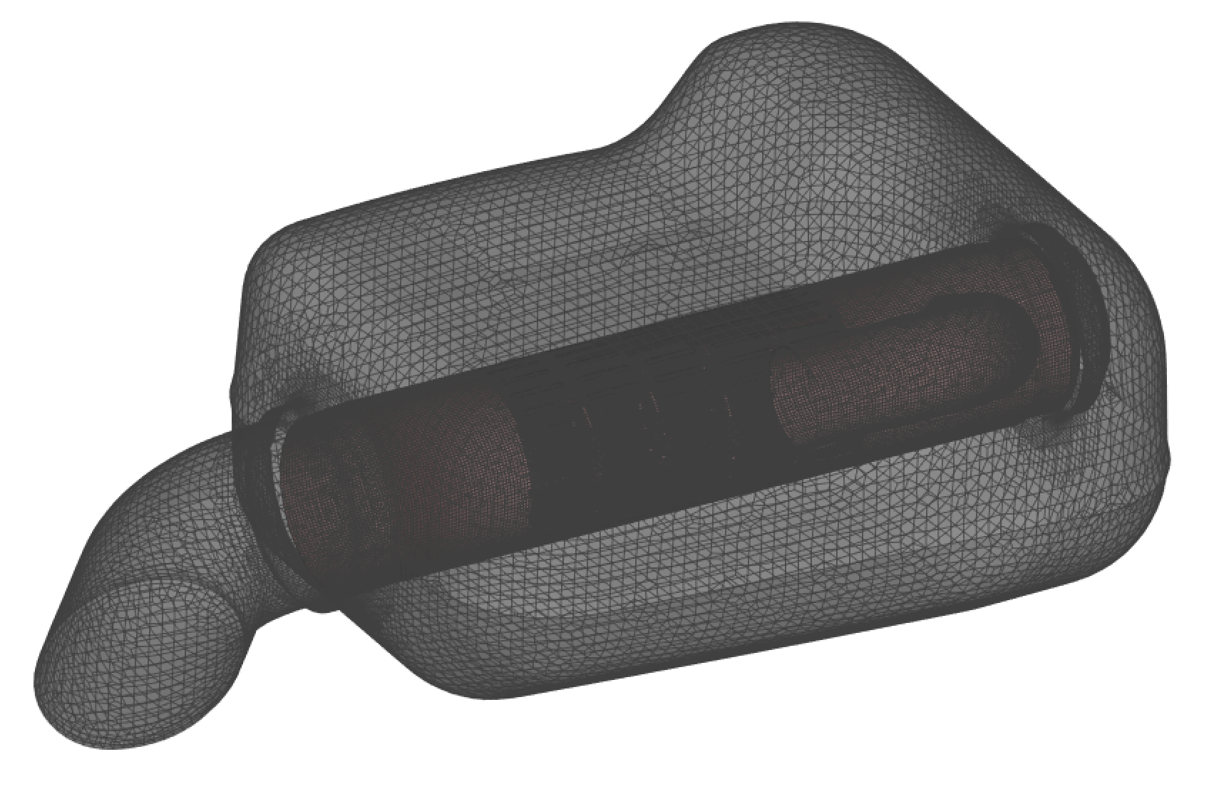
A multi-domain meshing feature enables generation of conformal interfaces between the multiple domains present in the geometry to be meshed. In addition, the method consistently handles baffles. It is available switching on the meshing of multiple domains and baffles feature in the settings tree.
The feature enables creation of both patches or face zones at multi-material interface and you can choose the case that is best for your type of simulation. In general, baffles are best to be left as patches and multi-material interfaces are often not needed unless they are moving or rotating.
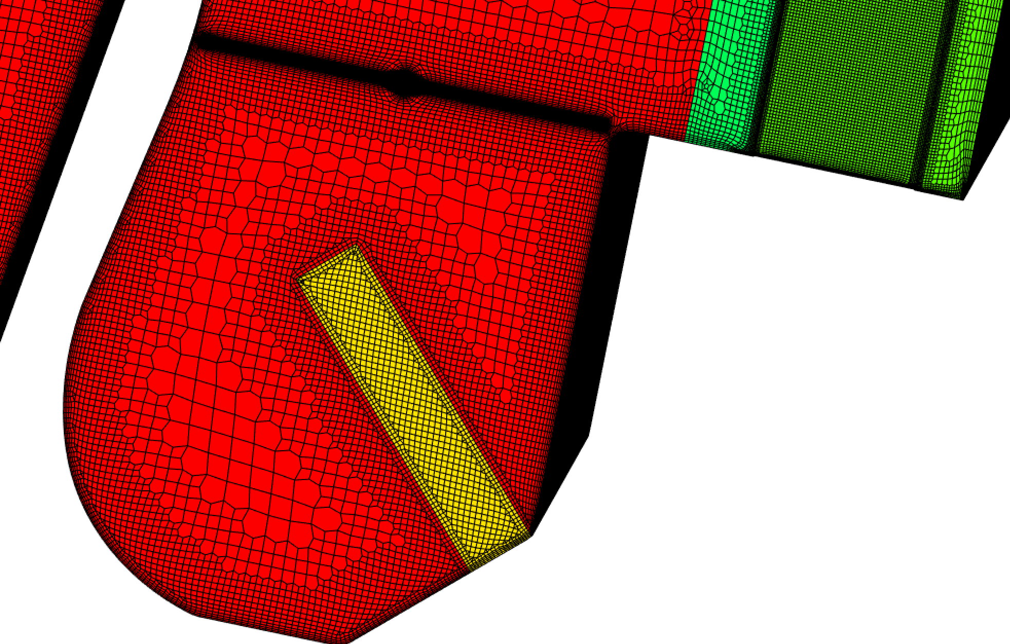
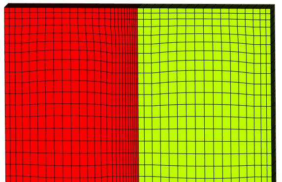
Consistent handling of internal interfaces can be used for generating anisotropic meshes where needed. For example, by defining the free surface as an internal interface it is possible to generate a fine high-quality boundary layer inside the mesh and greatly reduce the size of the mesh because it is not necessary to refine the mesh in all three spatial direction anymore. Another nice property is in alignment of the boundary layer with the geometry that also improves quality.
Boundary layer meshing is robust over internal interfaces. The layers check the topology of the interface and intersect wherever possible to generate the best possible layer topology and avoid collapsing of layers in most situations.
Additional information about CF-MESH+ is available in our online documentation.
3. AUTOMATIC MESHING WORKFLOWS
Starting from the input surface mesh triangulation (STL), CF-MESH+ produces meshes in a single run with simple prior setup. Implemented meshing algorithms are SMP parallelised and all CPU cores are used by default. The software is being continuously developed to reduce the user interaction to a minimum.
The meshing workflows are 3D, but there is also a possibility to create 2D volume meshes in the x-y plane (single cell depth in z direction) by using the Cartesian 2D meshing workflow.
There are the following automatic meshing workflows available in CF-MESH+:
Cartesian mesher (3D, 2D)
This workflow generates meshes consisting of predominantly hexahedral cells with polyhedra in transition regions between the cells of different size.
Hexahedral mesher (3D)
This workflow generates meshes consisting of hexahedral cells only.
Tetrahedral mesher (3D)
This workflow generates meshes consisting of tetrahedral cells only.
Polyhedral mesher (3D)
This workflow generates meshes consisting of arbitrary polyhedral cells.
4. MESH REFINEMENT
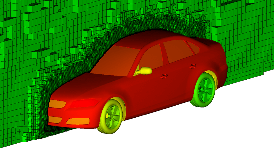
In CF-MESH+, the user can specify the regions for the volume mesh refinement. These regions can be boundaries in general, selected patches/faces/edges/vertices, primitive objects, and/or other (auxiliary) surface meshes. The user can specify the cell size or the number of refinement levels in these regions. This way one controls for the volume mesh density locally.
5. ANISOTROPIC MESHING
Quite often the nature of the simulated problem calls for anisotropic cells in order to generate more accurate solutions while minimizing the total cell count. The requirement for generating anisotropic cells is enabled in CF-MESH+ via primitive objects. The primitive objects that can be used for anisotropic meshing are boxes and planes.
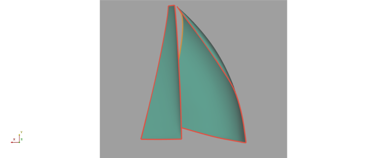
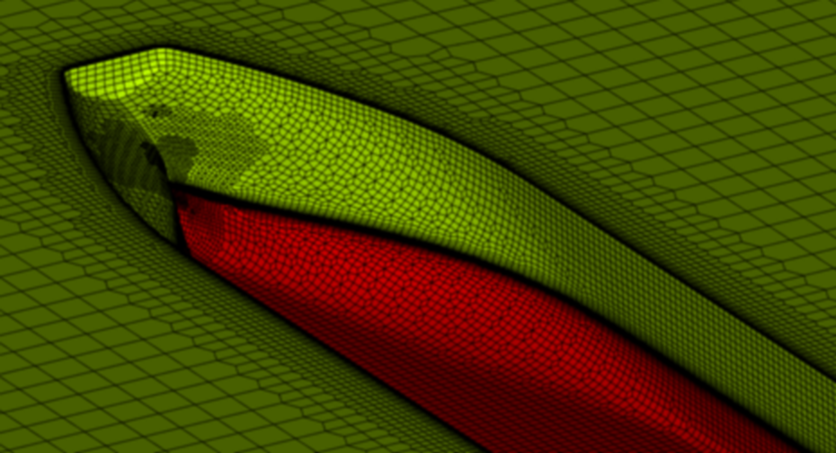
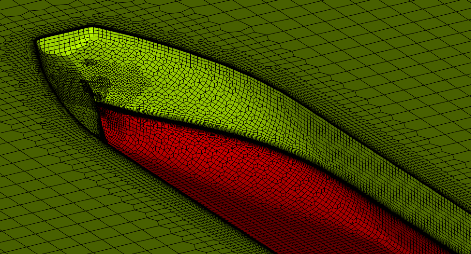
In the figure below one can see the screenshot of a mesh around the ship hull. The cells are visibly anisotropic and aligned with the expected flow direction.
DOWNLOAD EXAMPLES
CF-MESH+ in action
What’s new in the latest release
See what are our latest developments and which features are recently released
Choose your best solution

cfMesh (open source)
cfMesh is an open-source library for mesh generation implemented on top of the OpenFOAM® framework. Read more here.
Note: None of the OpenFOAM® related offering by Creative Fields Holding Ltd is approved or endorsed by OpenCFD, Ltd. (ESI Group), producer of the OpenFOAM® software. OpenFOAM® and OpenCFD® are registered trade marks of ESI Group.
Basic automatic cell sizing
Boundary layers
Cartesian 2D + 3D
Open source
Polyhedral meshing
Tetrahedral meshing

CF-MESH+ (pro)
Discover superior boundary layer generation capabilities, all in an affordable, automated, easy-to-use software.

