This study demonstrates automatic mesh generation on a simplified 3D model of The White House using CF-MESH+. The study shows the features enabling quick generation of the computational domain and refinement regions, needed to generate a quality mesh. The quality of the generated mesh was tested by performing a numerical simulation of a flow around the house, so some of the results are presented in addition.
1 Test case
1.1 Geometry preparation
The model was downloaded as a part of the Meshing Contest @ the International Meshing Roundtable 25. The model is given in four formats: SLDPRT, JT, STEP, and IGS. First, the surfaces were extracted from the STEP file in .stl file format and imported because CF-MESH+ requires geometry represented in a surface triangulation form as an input (FMS, FTR, or STL file format). Figure 1 shows the model of The White House.
*Here you can find more tips and tricks on how to prepare your geometry and provide meaningful settings.
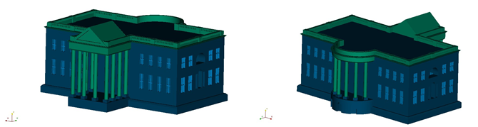
Figure 1: A front view of the White House (a) and a back view (b).
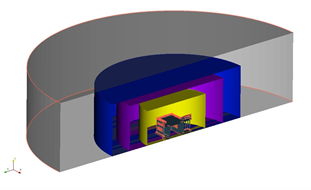
Then it was necessary to create a bounding box, domain for the simulation. The domain was created as a cylinder consisting of a top, floor, and curved surface (hollow cylinder). Figure 2 shows the bounding cylinder.
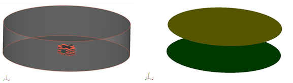
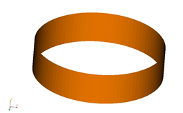
Figure 2: Cylindrical domain (a), top and floor surfaces (b), and the curved surface of the cylinder
(c).
At this stage, the domain consists of four surfaces: the top surface, the floor surface, the house, and the curved surface. The curved surface is named In out because it will serve as an inlet/outlet patch, the top surface is named Top patch, the floor surface is Floor patch and the house is House patch.
Furthermore, it is advisable to extract feature edges for better quality of edges in a mesh. It can be done automatically by clicking the right mouse button then Feature edges selection -> Auto-select edges.
Now the mesh can be generated, but to get better quality, some surfaces will be selected and grouped into face subsets. A face subset can be created by clicking the right mouse button then under Face selection choose some of the selection methods. After desired faces are selected, they have to be added to a new or existing subset by clicking the right mouse button and then Add facets to subset option. A subset can be given a new name so the new subset will be created or it can be chosen as one of the existing subsets so the faces will just be added to the existing subset.
In that way, all similar features around which are necessary to have a good quality mesh were grouped into the subsets: windows, fence on the roof, rooftop, pillars, bases of pillars, and some walls.
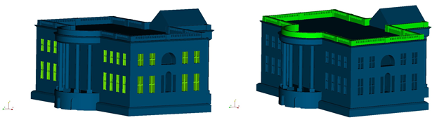
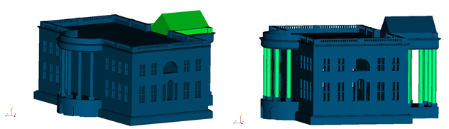
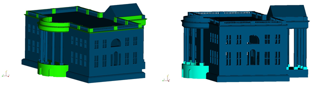
Figure 3: A closer view of the subsets: windows (a), fence on the roof (b), rooftop (c), pillars (d), walls (e), and pillar bases (f).
For the good quality mesh, it is also required to have some reasonably small cells in the areas where significant gradients of various physical quantities are expected to appear or the geometry requires fine cells due to small features.
A global cell size is selected under the Master settings and it is often chosen to have a coarse mesh away from the object of interest. The region near the house is refined using the facet subsets to refine small features at the geometry and the cylinder refinement source is used to refine the mesh near the house. It is advisable to create the cylinder such that the transition between the fine and the coarse cells occurs outside of the region of interest, and especially away from the feature edges.
In that manner, additional refinement zones in the domain (besides the face subsets) are defined. Here it is done by creating primitive objects inside which a refinement level will be defined. Primitive objects are created by right-clicking on the Primitives and then choosing Primitive under the Add selection.
In this case, the three cylinders as the primitive objects were added. Figure 4 shows the primitives in the domain.
1.2 Mesh Generation
After the maximum cell size is set, available under the Master settings (on the right in the Settings tree), it is then possible to set the remaining refinement regions using the face subsets and primitives, because the cell size that can be specified there is a multiplier of two.
The refinement settings for the face subsets are defined under Patches and subsets in the Refinement sources option in the mesh settings tree on the right.
Also, the refinement settings for the primitives are defined under the Primitive objects in the Refinement sources option in the mesh settings tree.
In Figures 5 and 6, a view of the generated mesh is shown. Figures 5 and 6 show the domain and some details and the refinement zone defined by the cylinders. Figure 7 shows the refinement regions defined by the face subsets.
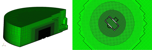
Figure 5: A view of the mesh: clipped domain (a), a zoomed view of the refinement zones with the primitives (b).
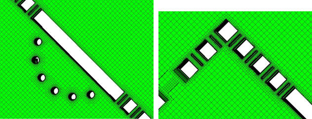
Figure 6: A view of the refinements around the house.
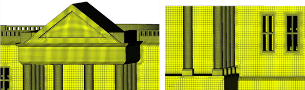
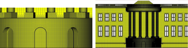
Figure 7: A view of the mesh around the roof (a), pillars (b), pillar bases (c), and a back view of the house mesh (d).
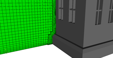
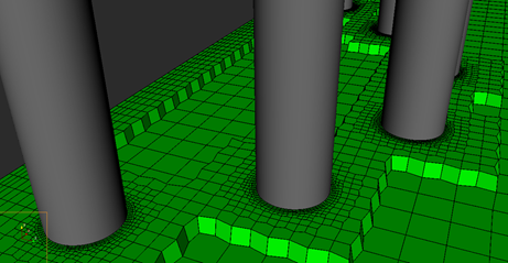
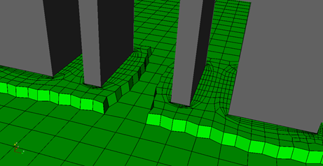
Figure 8: A closer look to Boundary layers
1.3 Numerical Simulation
The simulation models a turbulent airflow around the house using the kOmega SST turbulence model. The simulation is solved using simpleFoam, where a quasi-steady solution was obtained.
The curved surface of the cylindric domain is used as the inletOutlet patch where the inlet value of an airflow velocity is (4 0 4). Figures 9 and 10 show the velocity magnitude and pressure fields in the domain and around the house.
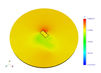
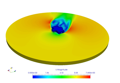
Figure 9: Pressure field (a) and velocity magnitude field (b) in the domain and around the house.
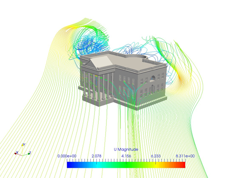
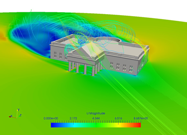
Figure 10: Velocity magnitude streamlines.
2 Conclusion
This report presented how to create a quality mesh around a complex geometry as The White House using the face subsets and primitives as the refinement sources, and zones. The final mesh was put to the test in the numerical simulation. The simulation converged to a quasi-steady solution where the expected results were obtained.
We hope that you have found this post useful and that it has made you curious to try out our latest CF-MESH+, designed to alleviate the pain of meshing. You can also subscribe to our newsletter to stay informed on our newest developments.
Mirna Barać, Danijel Bosnar, Karlo Jurina and dr.sc. Franjo Juretić
")
