1 Introduction
The present report deals with user-friendly automatic hex-dominant mesh generation on a Formula One model of industrial importance. The mesh generation is carried out using CF-MESH+ software. Also, many CF-MESH+ features and settings were shown and explained by examples.
2 Test case
2.1 Introduction
The goal of this Chapter is to show the capabilities of CF-MESH+ utilization for purposes of detailed automatic hex-dominant mesh generation. CF-MESH+ is the core product of Creative Fields Holding Ltd. The study is conducted on a 16 GB RAM machine with a 3.20GHz x 4 Intel Core i5 processor. In our other blog posts, you can read more about tips and tricks on how to prepare your geometry and provide meaningful settings.
2.2 Description of the Geometry
Within this study, a detailed STL model of the Ferrari F1 car (Figure 1a) is used. This model was created by Art Iskander and published on GrabCAD, a digital manufacturing hub. As one can notice, on the wheel rim (Figure 1b) a modification is needed to generate a mesh more suitable for CFD analysis. To accomplish this, we first defined the wheels as subsets using CF-MESH+. More information about facet subsets and their importance is given in Section 2.3. Then we extracted the wheels as separate STL files with the copySurfaceParts utility. Extraction of the back left wheel is shown in Listing 1.
Listing 1 Part extraction from the model
1: copySurfaceParts
FormulaOneCar.fms backLeftWheel.stl backleftWheel
After this is done, the repair of the STL is carried out utilizing:
- OpenSCAD for generation of the truncated elliptical cone which is embedded into the wheel to complete the wheel rim.
- Meshmixer for adjusting the generated truncated cone in the wheel.
- MeshLab for merging the wheel and the truncated cone.
Still, the truncated elliptical cone’s base and top have to be removed. Prior to the removal process, they should be defined as subsets in CF-MESH+. The removal is done via the removeSurfaceFacets utility. An example of removing the base on the back left wheel named backLeftWheel_outer is given in Listing 2.
Listing 2 Removing parts from the added geometrical entity
1: removeSurfaceFacets backLeftWheel_merged.fms backLeftWheel_mergedModified.fms backLeftWheel_outer
The next step is to merge the repaired parts with the original geometry. This is done utilizing the joinSurfaceMeshes utility and is shown in Listing 3.
Listing 3 Joining repaired parts with the original geometry
1: joinSurfaceMeshes FormulaOneCar.fms
-surfaceNames’( backLeftWheel_noWallsAtAll.fms
backRightWheel_noWallsAtAll.fms
frontLeftWheel_noWallsAtAll.fms
frontRightWheel_noWallsAtAll.fms
FormulaOne.fms
)’
Furthermore, the connection between the ground and the wheels is established by introducing small boxes with round corners. This modification task is also done using the aforementioned software. The accomplishment of this task results in the model shown in Figure 2. In order to make a stringent test of CF-MESH+ capabilities, the geometry modification is done without forcing perfect alignment of the added part with the base part as depicted in Figure 3.
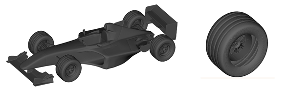
Figure 1: A view of the Formula One car (a) and the wheel (b).
An emphasis is put on taking into account all the details provided with the original CAD model. The details are highlighted with different colors in Figure 4 and, among others, include wheel rims, rear-view mirrors, and steering wheel. The colors refer to different facet subset entities.
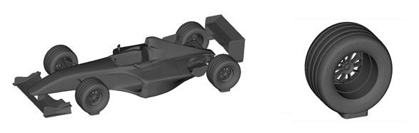
Figure 2: A view of the Formula One car (a) and the wheel (b) after modification is done.
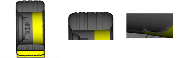
Figure 3: Yellow colour denotes elements that are merged to the original geometry (a). Not perfect alignment of the merged cone at its top and base (b). At the back right wheel, the geometry is not watertight due to the existence of a small passage (c).
2.3. Mesh Generation
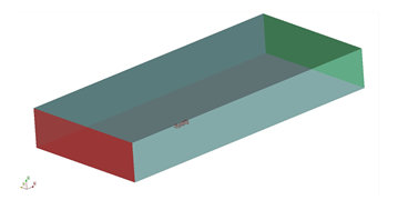
The mesh generation settings are defined within the meshDict file located in the system folder. The meshDict file can be nicely modified via the CF-MESH+ graphical interface. Prior to the meshing process, one should import the car geometry and generate an appropriate bounding box as shown in Figure 5. The following patches are assigned to the sides of the defined bounding box: inlet (marked red), outlet (marked green), sides (marked blue), and floor (marked gray). Also, the car geometry is included in the car patch.
After the bounding box is defined one can focus on the mesh generation within the car region. Since the geometry possesses a high level of detail, the use of facet subsets becomes mandatory. The facet subsets are user-defined entities located on the surface mesh where the user wants to have greater control of the refinement level. A clear description of how a subset can be easily defined is depicted in Figures 6 and 7. In this manner, the subsets are defined in all areas of interest. Some of those zones are shown in Figure 4.
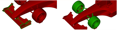
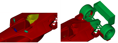
Figure 4: A closer view of the subsets: (a) front spoiler, (b) front suspension, (c) steering wheel, rear-view mirrors, part of engine cover, and (d) rear suspension. To establish better contrast, the Formula One car is marked red.
Can overlap, as depicted in Figure 8. In the case of overlapping subsets, the one with a higher refinement level has the greater priority (Figure 8d). The final surface mesh of the Formula One car is shown in Figure 9. Figure 10 gives insight into the surface mesh of the front wing and wheel rim as well as the mesh of the wheel interior and the front suspension’s cross-section.
The final surface mesh of the Formula One car is shown in Figure 9. Figure 10 gives insight into the surface mesh of the front wing and wheel rim as well as the mesh of the wheel interior and the front suspension’s cross-section. Although the elements added within the mesh modification process intersect the input geometry (Figures 3a and 3b), CF-MESH+ removes unnecessary parts and makes a sharp geometry representation (Figure 10c).
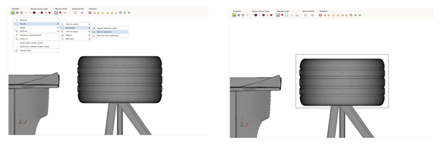
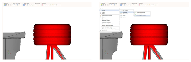
Figure 6: Choosing the rectangular selection for taking the complete wheel (a). Selection of the wheel (b). Additional captured parts are consequences of the input geometry STL triangulation (c). Removing the extra parts with Remove from selection option (d).
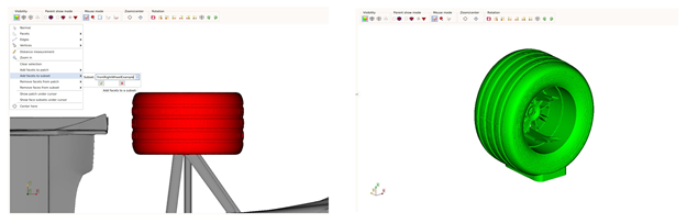
Figure 7: Additional triangles are removed and the subset is made from the selection (a). 3D view of the generated subset (b).
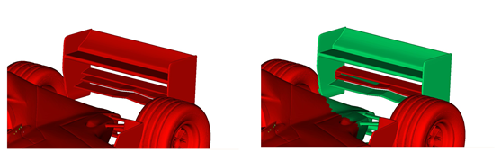
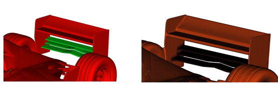
Figure 8: Rear spoiler (a). Subset which takes into account rear suspension part (b). The rear spoiler subset overlaps with the rear suspension subset (c). The subset with a higher level of refinement is kept in the overlapping region (d).
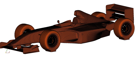
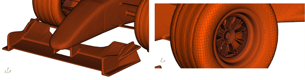
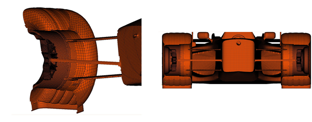
Figure 10: Detailed view of the front spoiler surface mesh (a). Discretized front left wheel with increased resolution at the rim (b). The front right wheel’s interior (c). Cross-sectional view at the front suspension (d).
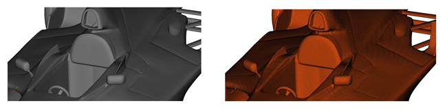
Figure 11: Geometry (a) and discretization (b) of the rearview mirrors, steering wheel, and a part of the engine cover.
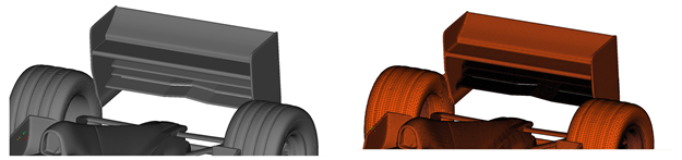
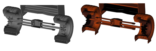
Figure 12: Input geometry (a) and the surface mesh (b) of the Formula One rear part. Cross section of the original (c) and discretized (d) rear suspension.
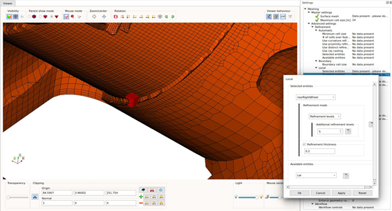
In the last Section, the existence of the small passage at the rear right wheel is shown (Figure 3c). Because of this, the wheel geometry is not watertight. But, if the applied refinement level is coarse enough this hole would be closed (Figure 13b). The refinement level can be easily inspected in advance via the CF-MESH+ graphical interface. An example is shown in Figure 14.
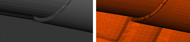
Figure 13: The small gap that makes the original geometry not watertight (a) is resolved by CF-MESH+ (b).
The complete mesh (Figure 15) consists of 11570913 cells where 11214472 cells (96.92%) are hexahedral cells. Then, there are 337234 (2.91%) polyhedral cells, 11012 (0.10%) prisms, 4386 (0,04%) pyramids, and 3809 (0,03%) tetrahedral cells. In order to capture gradients that occur in the vicinity of the analysed car, the mesh is refined via refinement boxes (dark blocks in Figure 15) defined with the objectRefinement dictionary. A closed view on the clipped domain (Figure 16) shows applied mesh refinement in the car region as well as a three-layered boundary layer at the floor (Figure 16c) and a five-layered boundary layer at the car. Furthermore, the CF-MESH+ visualisation capabilities together with the mesh resolution at the different parts are demonstrated in Figures 17-20.
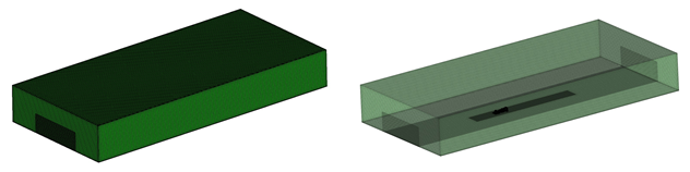
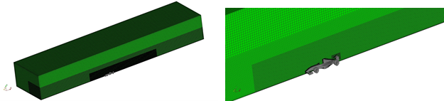
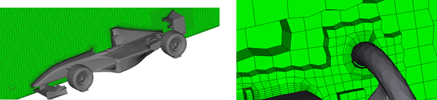
Figure 16: A clipped view of the domain while keeping the input geometry (a-b). The mesh refinement in the immediate neighbourhood of the car (c). The boundary layers are generated on the whole geometry and even on highly curved small parts such as the steering wheel (d). Note that clipping in CF-MESH+ is by default followed by visualization of the entire cells.
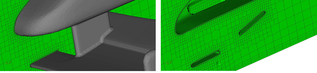
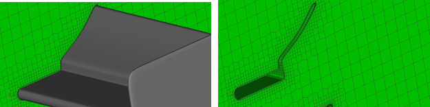
Figure 17: A detailed view of the mesh adjacent to the front spoiler (a-b) and the rear spoiler (c-d). The five layers of boundary layers at the car and the three layers at the floor are visible.
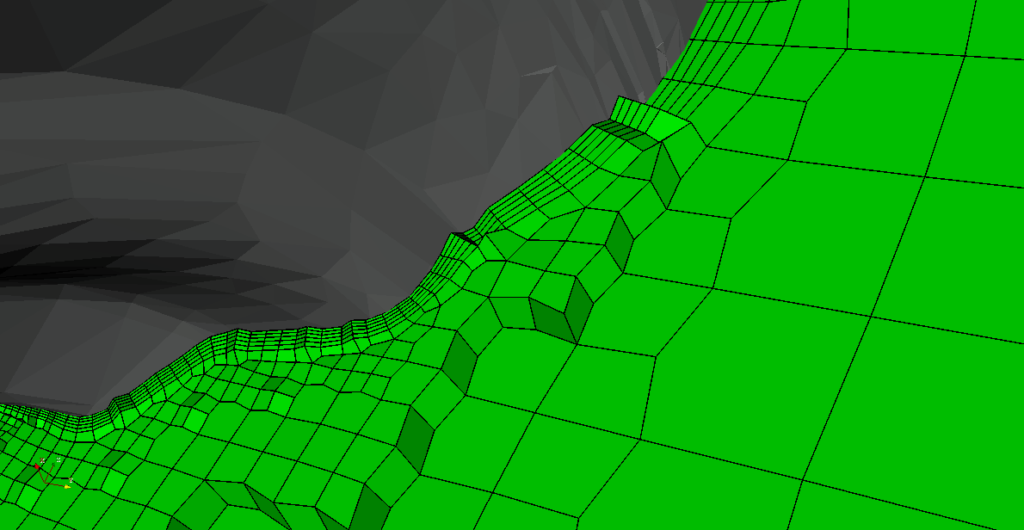
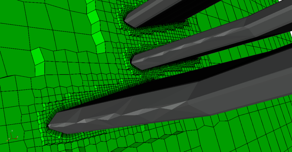
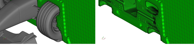
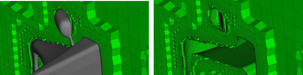
Figure 19: The volume mesh of the wheels and front suspension (a-b) together with the mesh of the right rear view mirror (c-d). The dark part near the geometry is a five-layered boundary layer. Also, in (a-b) one can recognize three layered boundary layers at the floor.
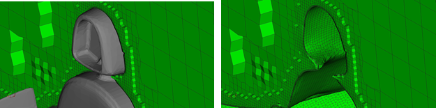
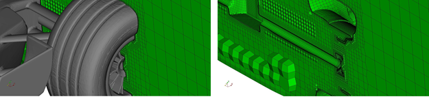
Figure 20: The details of the volume mesh at the engine cover top (a-b) and the rear left wheel (c-d). The boundary layers are completely adjusted to the geometry.
I hope that you have found this post useful and that it has made you curious to try out our latest CF-MESH+, designed to alleviate the pain of meshing. You can also subscribe to our newsletter to stay informed on our newest developments.
Acknowledgment
The authors would like to thank Mr. Art Iskander for allowing us to use the Formula One STL model.
By Alen Cukrov, dr.sc. Franjo Juretić and Karlo Jurina
")
